 |
am6zzn00005878
INSTRUMENTATION/DRIVER INFO.
id092200018200
Outline
Specification
TYPE A
|
Item |
Specification |
|||||||||
|---|---|---|---|---|---|---|---|---|---|---|
|
Instrument cluster
|
Warning lights
|
Brightness (cd/m 2)
|
200―300
|
|||||||
|
Light source
|
LED
|
|||||||||
|
Indicator light
|
Brightness (cd/m 2)
|
18―300
|
||||||||
|
Light source
|
LED
|
|||||||||
|
Warning beep
|
Oscillation frequency (Hz)
|
1,500―2,000
|
||||||||
|
Output sound pressure (dB)
|
65―80
|
|||||||||
|
Display sound
|
Oscillation frequency (Hz)
|
1,300―1,500
|
||||||||
|
Output sound pressure (dB)
|
70―80
|
|||||||||
|
Speedometer
|
System
|
Digital type
|
||||||||
|
Display
|
Multi-information display
|
|||||||||
|
Input signal communication system
|
CAN system
|
|||||||||
|
Tachometer
|
System
|
Stepping motor type
|
||||||||
|
Display
|
Analog needle
|
|||||||||
|
Input signal communication system
|
CAN system
|
|||||||||
|
High engine coolant temperature warning light (red)/High engine coolant temperature warning indication/Low engine coolant temperature indicator light (blue)
|
Operation
|
|||||||||
|
Input signal communication system
|
CAN system
|
|||||||||
|
Instrument cluster
|
Fuel gauge
|
System
|
Stepping motor type
|
|||||||
|
Display
|
Analog needle
|
|||||||||
|
Input signal source
|
Fuel gauge sender unit
|
|||||||||
|
Analog needle indication
|
E-STOP
|
E- POINT
|
1/4
|
1/2
|
3/4
|
F-POINT
|
F-STOP
|
|||
|
Remaining fuel quantity (L {US gal, Imp gal}) in fuel tank
|
2WD
|
0—6 {0—1, 0—1}
|
6—18 {2.0—4.7, 2.0—3.9}
|
18—31 {4.8—8.1, 4.0—6.8}
|
31—43 {8.2—11.0, 6.9—9.4}
|
43—56 {12—14, 9.5—12.0}
|
56—59 {14—15.5, 12.4—12.9}
|
59—62 {15.6—16.3, 13—13.6}
|
||
|
4WD
|
0—6 {0—1, 0—1}
|
6—16 {2.0—4.2, 2.0—3.5}
|
16—26 {4.3—6.8, 3.6—5.7}
|
26—37 {6.9—9.7, 5.8—8.1}
|
37—47 {9.8—12, 8.2—10.0}
|
47—50 {12.5—13.2, 10.4—10.9}
|
50—52 {13.3—13.7, 11—11.4}
|
|||
|
Remaining fuel level (L {US gal, Imp gal}) when low fuel warning indication turns on
|
Approx. 10 {2.6, 2.2}
|
|||||||||
|
Invalid remaining fuel level (L {US gal, Imp gal})
|
Approx. 0.81 {0.21, 0.18}
|
|||||||||
|
Engine coolant temperature gauge
|
System
|
Stepping motor type
|
||||||||
|
Display
|
Analog needle
|
|||||||||
|
Input signal communication system
|
CAN system
|
|||||||||
|
Odometer
|
System
|
Digital type
|
||||||||
|
Display
|
Multi-information display
|
|||||||||
|
Display area
|
0—999999
|
|||||||||
|
Minimum display unit (km/mile)
|
1
|
|||||||||
|
Input signal communication system
|
CAN system
|
|||||||||
|
Tripmeter
|
System
|
Digital type
|
||||||||
|
Display
|
Multi-information display
|
|||||||||
|
Display area
|
0—1999
(Returns to 0 from 1999, calculation continues)
|
|||||||||
|
Minimum display unit (km/mile)
|
1
|
|||||||||
|
Input signal communication system
|
CAN system
|
|||||||||
|
Horn
|
Horn LO
|
Oscillation frequency (Hz)
|
390―440
|
|||||||
|
Waveform
|
Spiral
|
|||||||||
|
Horn HI
|
Oscillation frequency (Hz)
|
470―530
|
||||||||
|
Waveform
|
Spiral
|
|||||||||
TYPE B
|
Item |
Specification |
|||||||||||||||||||
|---|---|---|---|---|---|---|---|---|---|---|---|---|---|---|---|---|---|---|---|---|
|
Instrument cluster
|
Warning lights
|
Brightness (cd/m 2)
|
155―345
|
|||||||||||||||||
|
Light source
|
LED
|
|||||||||||||||||||
|
Indicator light
|
Brightness (cd/m 2)
|
14―345
|
||||||||||||||||||
|
Light source
|
LED
|
|||||||||||||||||||
|
Warning beep
|
Oscillation frequency (Hz)
|
1,500―2,000
|
||||||||||||||||||
|
Output sound pressure (dB)
|
65―80
|
|||||||||||||||||||
|
Display sound
|
Oscillation frequency (Hz)
|
1,300―1,500
|
||||||||||||||||||
|
Output sound pressure (dB)
|
70―80
|
|||||||||||||||||||
|
Speedometer
|
System
|
Stepping motor type
|
||||||||||||||||||
|
Display
|
Analog needle
|
|||||||||||||||||||
|
Input signal communication system
|
CAN system
|
|||||||||||||||||||
|
Tachometer
|
System
|
Stepping motor type
|
||||||||||||||||||
|
Display
|
Analog needle
|
|||||||||||||||||||
|
Input signal communication system
|
CAN system
|
|||||||||||||||||||
|
High engine coolant temperature warning light (red)/High engine coolant temperature warning indication/Low engine coolant temperature indicator light (blue)
|
Operation
|
|||||||||||||||||||
|
Input signal communication system
|
CAN system
|
|||||||||||||||||||
|
Instrument cluster
|
Fuel gauge
|
System
|
Digital type
|
|||||||||||||||||
|
Display
|
Multi-information display
|
|||||||||||||||||||
|
Input signal source
|
Fuel gauge sender unit
|
|||||||||||||||||||
|
Digital needle indication
|
1
|
2
|
3
|
4—6
|
7
|
8—14
|
15
|
16—26
|
27
|
28—38
|
39
|
40—45
|
46
|
47—50
|
51
|
52
|
53
|
|||
|
Remaining fuel quantity (L {US gal, Imp gal}) in fuel tank
|
0—4 {0—4, 0—3}
|
4—5 {1.1—1.3, 0.9—1.0}
|
5—6 {1.4—1.5, 1.1—1.3}
|
6—10 {2.0—2.6, 2.0—2.1}
|
10—11 {2.7—2.9, 2.2—2.4}
|
11—19 {3.0—5.0, 2.5—4.1}
|
19—20 {5.1—5.2, 4.2—4.3}
|
20—33 {5.3—8.7, 4.4—7.2}
|
33—34 {8.8—8.9, 7.3—7.4}
|
34—47 {9.0—12.0, 7.5—10.0}
|
47—48 {12.5—12.6, 10.4—10.5}
|
48—55 {13—14, 11—12}
|
55—56 {14.6—14.7, 12.1—12.3}
|
56—60 {14.8—15.8, 12.4—13.1}
|
60—61 {15.9—16.1, 13.2—13.4}
|
61—63 {16.2—16.6, 13.5—13.8}
|
63—72 {17—19, 14—15}
|
|||
|
Remaining fuel level (L {US gal, Imp gal}) when low fuel warning indication turns on
|
Approx. 11 {2.9, 2.4}
|
|||||||||||||||||||
|
Invalid remaining fuel level (L {US gal, Imp gal})
|
Approx. 0.81 {0.21, 0.18}
|
|||||||||||||||||||
|
Engine coolant temperature gauge
|
System
|
Digital type
|
||||||||||||||||||
|
Display
|
Multi-information display
|
|||||||||||||||||||
|
Input signal communication system
|
CAN system
|
|||||||||||||||||||
|
Odometer
|
System
|
Digital type
|
||||||||||||||||||
|
Display
|
Multi-information display
|
|||||||||||||||||||
|
Display area
|
0—999999
|
|||||||||||||||||||
|
Minimum display unit (km/mile)
|
1
|
|||||||||||||||||||
|
Input signal communication system
|
CAN system
|
|||||||||||||||||||
|
Tripmeter
|
System
|
Digital type
|
||||||||||||||||||
|
Display
|
Multi-information display
|
|||||||||||||||||||
|
Display area
|
0—1999
(Returns to 0 from 1999, calculation continues)
|
|||||||||||||||||||
|
Minimum display unit (km/mile)
|
1
|
|||||||||||||||||||
|
Input signal communication system
|
CAN system
|
|||||||||||||||||||
|
Horn
|
Horn LO
|
Oscillation frequency (Hz)
|
390―440
|
|||||||||||||||||
|
Waveform
|
Spiral
|
|||||||||||||||||||
|
Horn HI
|
Oscillation frequency (Hz)
|
470―530
|
||||||||||||||||||
|
Waveform
|
Spiral
|
|||||||||||||||||||
TYPE C
|
Item |
Specification |
||||||||||||||||||
|---|---|---|---|---|---|---|---|---|---|---|---|---|---|---|---|---|---|---|---|
|
Instrument cluster
|
Warning lights
|
Brightness (cd/m 2)
|
200―300
|
||||||||||||||||
|
Light source
|
LED
|
||||||||||||||||||
|
Indicator light
|
Brightness (cd/m 2)
|
18―300
|
|||||||||||||||||
|
Light source
|
LED
|
||||||||||||||||||
|
Warning beep
|
Oscillation frequency (Hz)
|
1,500―2,000
|
|||||||||||||||||
|
Output sound pressure (dB)
|
65―80
|
||||||||||||||||||
|
Display sound
|
Oscillation frequency (Hz)
|
1,300―1,500
|
|||||||||||||||||
|
Output sound pressure (dB)
|
70―80
|
||||||||||||||||||
|
Speedometer
|
System
|
Stepping motor type
|
|||||||||||||||||
|
Display
|
Analog needle
|
||||||||||||||||||
|
Input signal communication system
|
CAN system
|
||||||||||||||||||
|
Tachometer
|
System
|
Stepping motor type
|
|||||||||||||||||
|
Display
|
Analog needle
|
||||||||||||||||||
|
Input signal communication system
|
CAN system
|
||||||||||||||||||
|
Instrument cluster
|
Fuel gauge
|
System
|
Digital type
|
||||||||||||||||
|
Display
|
LCD
|
||||||||||||||||||
|
Input signal source
|
Fuel gauge sender unit
|
||||||||||||||||||
|
Digital needle indication
|
E
|
1
|
2
|
3
|
4
|
5
|
6
|
7
|
8
|
9
|
10
|
11
|
12
|
13
|
14
|
15
|
|||
|
Remaining fuel quantity (L {US gal, Imp gal}) in fuel tank
|
0—6 {0—1, 0—1}
|
6—9 {1.6—2.3, 1.4—1.9}
|
9—11 {3.0—2.9, 2.0—2.4}
|
11—13 {3.0—3.4, 2.5—2.8}
|
13—15 {3.5—3.9, 2.9—3.2}
|
15—17 {4.0—4.4, 3.3—3.7}
|
17—19 {4.5—5.0, 3.8—4.1}
|
19—23 {5.1—6.0, 4.2—5.0}
|
23—28 {6.1—7.3, 5.1—6.1}
|
28—32 {7.4—8.4, 6.2—7.0}
|
32—36 {8.5—9.5, 7.1—7.9}
|
36—40 {9.6—10.0, 8.0—8.7}
|
40—44 {10.6—11.6, 8.8—9.6}
|
44—48 {11.7—12.6, 9.7—10.0}
|
48—53 {13—14, 10.6—11.6}
|
53—62 {15—16, 12—13}
|
|||
|
Remaining fuel level (L {US gal, Imp gal}) when low fuel warning light turns on
|
Approx. 11 {2.9, 2.4}
|
||||||||||||||||||
|
Invalid remaining fuel level (L {US gal, Imp gal})
|
Approx. 0.85 {0.22, 0.19}
|
||||||||||||||||||
|
Engine coolant temperature gauge
|
System
|
Digital type
|
|||||||||||||||||
|
Display
|
LCD
|
||||||||||||||||||
|
Input signal communication system
|
CAN system
|
||||||||||||||||||
|
Odometer
|
System
|
Digital type
|
|||||||||||||||||
|
Display
|
LCD
|
||||||||||||||||||
|
Display area
|
0—999999
|
||||||||||||||||||
|
Minimum display unit (km/mile)
|
1
|
||||||||||||||||||
|
Input signal communication system
|
CAN system
|
||||||||||||||||||
|
Tripmeter
|
System
|
Digital type
|
|||||||||||||||||
|
Display
|
LCD
|
||||||||||||||||||
|
Display area
|
0.0—9999.9
(Returns to 0.0 from 9999.9, calculation continues)
|
||||||||||||||||||
|
Minimum display unit (km/mile)
|
0.1
|
||||||||||||||||||
|
Input signal communication system
|
CAN system
|
||||||||||||||||||
|
Horn
|
Horn LO
|
Oscillation frequency (Hz)
|
390―440
|
||||||||||||||||
|
Waveform
|
Spiral
|
||||||||||||||||||
|
Horn HI
|
Oscillation frequency (Hz)
|
470―530
|
|||||||||||||||||
|
Waveform
|
Spiral
|
||||||||||||||||||
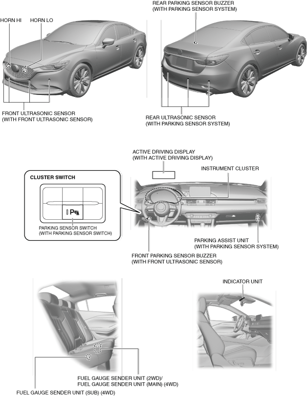
Structure/Construction
Structural view
am6zzn00005878
|