ON-BOARD DIAGNOSTIC [INSTRUMENT CLUSTER]
id092200021843
Outline
• The on-board diagnostic function consists of the following functions: a malfunction detection function, which detects overall malfunctions in the instrument cluster-related parts; a memory function, which stores detected DTCs; a display function, which indicates malfunction locations and status via DTC output; and a PID/data monitoring function, which reads out specific input/output signals and verifies the input/output condition.
• Using the Mazda Modular Diagnostic System (M-MDS), DTCs can be read out and deleted, and the PID/data monitoring function can be activated.
Function
Malfunction detection function
-
• Detects malfunctions in input/output signals.
• If a malfunction occurs, the instrument cluster records the malfunction as a DTC. A recorded DTC can be read by the Mazda Modular Diagnostic System (M-MDS).
DTC table
×: Applicable
—: Not applicable
|
DTC No.
|
Warning/indicator light
|
Description
|
Fail-safe
|
Drive cycle
|
Self test type*1
|
Memory function
|
|
B11D4:53*2
|
—
|
Forward sensing camera (FSC) malfunction
|
×
|
—
|
C, D
|
×
|
|
U0001:88
|
—
|
Module communication error (HS-CAN)
|
—
|
—
|
C, D
|
×
|
|
U0010:88
|
—
|
Module communication error (MS-CAN)
|
—
|
—
|
C, D
|
×
|
|
U0100:00
|
Illuminated/Flash
|
Communication error with PCM
|
—
|
—
|
C, D
|
×
|
|
U0101:00*3
|
—
|
Communication error with TCM
|
—
|
—
|
C, D
|
×
|
|
U0104:00*4
|
Illuminated/Flash
|
Communication error with radar unit
|
—
|
—
|
C, D
|
×
|
|
U0114:00*5
|
—
|
Communication error with 4WD control module
|
—
|
—
|
C, D
|
×
|
|
U0121:00
|
Illuminated/Flash
|
Communication error with DSC HU/CM
|
—
|
—
|
C, D
|
×
|
|
U0128:00*6
|
Illuminated/Flash
|
Communication error with electric parking brake control module
|
—
|
—
|
C, D
|
×
|
|
U0131:00
|
Illuminated/Flash
|
Communication error with EPS control module
|
—
|
—
|
C, D
|
×
|
|
U0140:00
|
Illuminated/Flash
|
Communication error with front body control module (FBCM)
|
—
|
—
|
C, D
|
×
|
|
U0142:00
|
—
|
Communication error with rear body control module (RBCM)
|
—
|
—
|
C, D
|
×
|
|
U0151:00
|
Illuminated/Flash
|
Communication error with SAS control module
|
—
|
—
|
C, D
|
×
|
|
U0156:00*7
|
Illuminated/Flash
|
Communication error with connectivity master unit (CMU)
|
—
|
—
|
C, D
|
×
|
|
U0158:00*8
|
—
|
Communication error with active driving display
|
—
|
—
|
C, D
|
×
|
|
U0159:00*9
|
Illuminated/Flash
|
Communication error with parking assist unit
|
—
|
—
|
C, D
|
×
|
|
U0182:00
|
Illuminated/Flash
|
Communication error with adaptive LED headlights control module/auto leveling control module/adaptive front lighting system (AFS) control module
|
—
|
—
|
C, D
|
×
|
|
U0214:00
|
Illuminated/Flash
|
Communication error with start stop unit
|
—
|
—
|
C, D
|
×
|
|
U0232:00*10
|
Illuminated/Flash
|
Communication error with blind spot monitoring (BSM) control module (LH)
|
—
|
—
|
C, D
|
×
|
|
U0233:00*11
|
—
|
Communication error with blind spot monitoring (BSM) control module (RH)
|
—
|
—
|
C, D
|
×
|
|
U0235:00*12
|
—
|
Communication error with forward sensing camera (FSC)
|
×
|
—
|
C, D
|
×
|
|
U023A:00*13
|
Illuminated/Flash
|
Communication error with forward sensing camera (FSC)
|
—
|
—
|
C, D
|
×
|
|
U0298:00*14
|
—
|
Communication error with DC-DC converter (i-ELOOP)
|
—
|
—
|
C, D
|
—
|
|
U0300:00*15
|
—
|
Instrument cluster configuration error
|
—
|
—
|
C, D
|
×
|
|
U0401:68
|
Illuminated/Flash
|
Error signal received from PCM
|
—
|
—
|
C, D
|
×
|
|
U0402:68*3
|
—
|
Error signal received from transmission/transaxle
|
—
|
—
|
C, D
|
×
|
|
U0405:00*16
|
Illuminated/Flash
|
Error signal received from radar unit
|
—
|
—
|
C, D
|
×
|
|
U0422:68
|
Illuminated/Flash
|
Error signal received from front body control module (FBCM)
|
—
|
—
|
C, D
|
×
|
|
U045A:82*17
|
—
|
Error signal received from parking assist unit
|
—
|
—
|
C, D
|
×
|
|
U0515:68
|
Illuminated/Flash
|
Error signal received from start stop unit
|
—
|
—
|
C, D
|
×
|
|
U0533:68
|
—
|
Error signal received from blind spot monitoring (BSM) control module (LH)
|
—
|
—
|
C, D
|
×
|
|
U053B:00
|
Illuminated/Flash
|
Error signal received from forward sensing camera (FSC)
|
—
|
—
|
C, D
|
×
|
|
U2005:86
|
—
|
Error signal received from PCM
|
—
|
—
|
C, D
|
×
|
|
U2013:13
|
—
|
Cluster switch circuit malfunction
|
—
|
—
|
C, D
|
×
|
|
U2100:00
|
—
|
Instrument cluster configuration error
|
—
|
—
|
C, D
|
×
|
|
U2105:02*18
|
—
|
Drive selection switch circuit malfunction
|
—
|
—
|
C, D
|
×
|
|
U2300:41
|
—
|
Instrument cluster configuration error
|
—
|
—
|
C, D
|
×
|
|
U2300:51
|
—
|
Instrument cluster configuration error
|
—
|
—
|
C, D
|
×
|
|
U2300:56
|
—
|
Instrument cluster configuration error
|
—
|
—
|
C, D
|
×
|
|
U2300:57
|
—
|
Instrument cluster configuration error
|
—
|
—
|
C, D
|
×
|
|
U3000:41*15
|
—
|
Instrument cluster internal malfunction
|
—
|
—
|
C, D
|
×
|
|
U3003:16
|
—
|
Low power supply voltage input to instrument cluster
|
—
|
—
|
C, D
|
×
|
*1 :C: CMDTC self test, D: ODDTC self test
*2 :With smart city brake support (SCBS) (Instrument cluster (Type B))
*3 :ATX
*4 :With Mazda Radar Cruise Control (MRCC) system
*5 :4WD
*6 :Instrument cluster (Type A or C)
*7 :With center display (Instrument cluster (Type A or C))
*8 :With active driving display (Instrument cluster (Type A))
*9 :With parking assist system (Instrument cluster (Type A or C))
*10 :With blind spot monitoring (BSM) system (Instrument cluster (Type A or C))
*11 :With blind spot monitoring (BSM) system (Instrument cluster (Type B))
*12 :With smart city brake support (SCBS) (Instrument cluster (Type A or B))
*13 :With forward sensing camera (FSC) (Instrument cluster (Type A or C))
*14 :With i-ELOOP (Instrument cluster (Type A or C))
*15 :Instrument cluster (Type A or B)
*16 :With Mazda Radar Cruise Control (MRCC) system (Instrument cluster (Type B or C))
*17 :With parking assist system (Instrument cluster (Type C))
*18 :With drive selection switch (Instrument cluster (Type A or C))
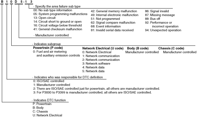
DTC 7-digit code definition
-
• When related systems or components have failed, the CM stores the DTC of the malfunctioning part in the CM memory, and allows for the retrieval of the store data using scanning tool when necessary. The DTCs are indicated using seven digits. Each digit indicates the following.
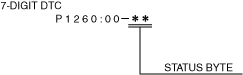
Status byte for DTC
-
• The status byte is the two digits (two digits after hyphen (-)) after the 7-digit DTC.
• The status byte is a code which indicates the pending code, current/past malfunction status, or warning illumination status.
• The status byte can be read by performing a CMDTC self-test using the Mazda Modular Diagnostic System (M-MDS).
• For details on the status byte, refer to the explanation on the Mazda Modular Diagnostic System (M-MDS) when reading the DTC.
Detection condition for the applicable DTC
×: Applicable
—: Not applicable
|
DTC No.
|
Description
|
Detection condition
|
|
B11D4:53*1
|
Forward sensing camera (FSC) malfunction
|
• Instrument cluster detects the following malfunctions:
-
― Forward sensing camera (FSC) malfunction
― Malfunction in smart city brake support related system (forward sensing camera (FSC), DSC HU/CM, PCM)
|
|
U0001:88
|
Module communication error (HS-CAN)
|
• Instrument cluster detects a CAN bus communication line (HS-CAN) malfunction.
|
|
U0010:88
|
Module communication error (MS-CAN)
|
• Instrument cluster detects a CAN bus communication line (MS-CAN) malfunction.
|
|
U0100:00
|
Communication error with PCM
|
• Instrument cluster cannot receive the CAN signal from the PCM.
|
|
U0101:00*2
|
Communication error with TCM
|
• Instrument cluster cannot receive the CAN signal from the TCM for 1 s or more.
|
|
U0104:00*3
|
Communication error with radar unit
|
• Instrument cluster cannot receive the CAN signal from the radar unit.
|
|
U0114:00*4
|
Communication error with 4WD control module
|
• Instrument cluster cannot receive CAN signal from the 4WD control module for 1 s or more.
|
|
U0121:00
|
Communication error with DSC HU/CM
|
• Instrument cluster cannot receive the CAN signal from the DSC HU/CM.
|
|
U0128:00*5
|
Communication error with electric parking brake control module
|
• Instrument cluster cannot receive the CAN signal from the electric parking brake control module for 1 s or more.
|
|
U0131:00
|
Communication error with EPS control module
|
• Instrument cluster cannot receive the CAN signal from the EPS control module for 1 s or more.
|
|
U0140:00
|
Communication error with front body control module (FBCM)
|
• Instrument cluster cannot receive the CAN signal from the front body control module (FBCM) for 5 s or more.
|
|
U0142:00
|
Communication error with rear body control module (RBCM)
|
• Instrument cluster cannot receive the CAN signal from the rear body control module (RBCM) for 5 s or more.
|
|
U0151:00
|
Communication error with SAS control module
|
• Instrument cluster cannot receive the CAN signal from the SAS control module for 2 s or more.
|
|
U0156:00*6
|
Communication error with connectivity master unit (CMU)
|
• Instrument cluster cannot receive the CAN signal from the connectivity master unit (CMU) for 5 s or more.
|
|
U0158:00*7
|
Communication error with active driving display
|
• Instrument cluster cannot receive the CAN signal from the active driving display for 5 s or more.
|
|
U0159:00*8
|
Communication error with parking assist unit
|
• Instrument cluster cannot receive the CAN signal from the parking assist unit for 5 s or more.
|
|
U0182:00
|
Communication error with adaptive LED headlights control module/auto leveling control module/adaptive front lighting system (AFS) control module
|
• Instrument cluster cannot receive the CAN signal from the adaptive LED headlights control module/auto leveling control module/adaptive front lighting system (AFS) control module for 5 s or more.
|
|
U0214:00
|
Communication error with start stop unit
|
• Instrument cluster cannot receive the CAN signal from the start stop unit.
|
|
U0232:00*9
|
Communication error with blind spot monitoring (BSM) control module (LH)
|
• Instrument cluster cannot receive the CAN signal from the blind spot monitoring (BSM) control module (LH) for 5 s or more.
|
|
U0233:00*10
|
Communication error with blind spot monitoring (BSM) control module (RH)
|
• Instrument cluster cannot receive the CAN signal from the blind spot monitoring (BSM) control module (RH) for 1.5 s or more.
|
|
U0235:00*11
|
Communication error with forward sensing camera (FSC)
|
• Instrument cluster cannot receive the CAN signal from the forward sensing camera (FSC).
|
|
U023A:00*12
|
Communication error with forward sensing camera (FSC)
|
• Instrument cluster cannot receive the CAN signal from the forward sensing camera (FSC).
|
|
U0298:00*13
|
Communication error with DC-DC converter (i-ELOOP)
|
• Instrument cluster cannot receive the CAN signal from the DC-DC converter (i-ELOOP).
|
|
U0300:00*14
|
Instrument cluster configuration error
|
• Instrument cluster configuration error (incorrect value write) detected.
|
|
U0401:68
|
Error signal received from PCM
|
• Instrument cluster receives the error signals from the PCM with the ignition switched ON (engine off or on).
|
|
U0402:68*2
|
Error signal received from transmission/transaxle
|
• Instrument cluster received the error signals from the transmission/transaxle for 1 s or more with the ignition switched ON (engine off or on).
|
|
U0405:00*15
|
Error signal received from radar unit
|
• Instrument cluster receives error signals from the radar unit with the ignition switched ON (engine off or on).
|
|
U0422:68
|
Error signal received from front body control module (FBCM)
|
• Instrument cluster receives the error signals from the front body control module (FBCM) for 5 s or more with the ignition switched ON (engine off or on).
|
|
U045A:82*16
|
Error signal received from parking assist unit
|
• The instrument cluster receives error signals from the parking assist unit for 5 s or more with the ignition switched ON (engine off or on).
|
|
U0515:68
|
Error signal received from start stop unit
|
• Instrument cluster receives the error signals from the start stop unit with the ignition switched ON (engine off or on).
|
|
U0533:68
|
Error signal received from blind spot monitoring (BSM) control module (LH)
|
• The instrument cluster receives error signals from the blind spot monitoring (BSM) control module (LH) for 5 s or more with the ignition switched ON (engine off or on).
|
|
U053B:00
|
Error signal received from forward sensing camera (FSC)
|
• The instrument cluster receives error signals from the forward sensing camera (FSC) for the ignition switched ON (engine off or on).
|
|
U2005:86
|
Error signal received from PCM
|
• Instrument cluster receives the vehicle speed signal error from the PCM for 1 s or more with the ignition switched ON (engine off or on).
|
|
U2013:13
|
Cluster switch circuit malfunction
|
• Instrument cluster detects an open circuit in the cluster switch circuit for 5 s or more with the ignition switched ON (engine off or on).
|
|
U2100:00
|
Instrument cluster configuration error
|
• Instrument cluster configuration error detected as follows:
-
― No configuration of instrument cluster
― Instrument cluster configuration has not been correctly performed.
|
|
U2105:02*17
|
Drive selection switch circuit malfunction
|
• Instrument cluster detects an open circuit in the drive selection switch circuit for 5 s or more with the ignition switched ON (engine off or on).
|
|
U2300:41
|
Instrument cluster configuration error
|
• Instrument cluster configuration error (data error) detected.
|
|
U2300:51
|
Instrument cluster configuration error
|
• Instrument cluster configuration error (no configuration) detected.
|
|
U2300:56
|
Instrument cluster configuration error
|
• Instrument cluster configuration error (incorrect value write) detected.
|
|
U2300:57
|
Instrument cluster configuration error
|
• Instrument cluster configuration error (data size error) detected.
|
|
U3000:41*14
|
Instrument cluster internal malfunction
|
• Instrument cluster detects the internal malfunction.
|
|
U3003:16
|
Low power supply voltage input to instrument cluster
|
• Instrument cluster power supply circuit voltage of less than 10 V is detected.
|
*1 :With smart city brake support (SCBS) (Instrument cluster (Type B))
*2 :ATX
*3 :With Mazda Radar Cruise Control (MRCC) system
*4 :4WD
*5 :Instrument cluster (Type A or C)
*6 :With center display (Instrument cluster (Type A or C))
*7 :With active driving display (Instrument cluster (Type A))
*8 :With parking assist system (Instrument cluster (Type A or C))
*9 :With blind spot monitoring (BSM) system (Instrument cluster (Type A or C))
*10 :With blind spot monitoring (BSM) system (Instrument cluster (Type B))
*11 :With smart city brake support (SCBS) (Instrument cluster (Type A or B))
*12 :With forward sensing camera (FSC) (Instrument cluster (Type A or C))
*13 :With i-ELOOP (Instrument cluster (Type A or C))
*14 :Instrument cluster (Type A or B)
*15 :With Mazda Radar Cruise Control (MRCC) system (Instrument cluster (Type B or C))
*16 :With parking assist system (Instrument cluster (Type C))
*17 :With drive selection switch (Instrument cluster (Type A or C))
Snapshot Data
• The data for all DTCs currently detected is stored.
Snapshot data table
—: Not applicable
|
Snapshot data item
|
Unit
|
Data contents
|
Data read/use method
|
Corresponding data monitor items
|
|
AAT
|
°C
|
°F
|
Ambient temperature
|
—
|
—
|
|
APP_STATUS
|
Accelerator Pedal Off/Under20%/Over20%/FAIL
|
Accelerator pedal position status
|
—
|
—
|
|
CFG_STATUS
|
Config Complete/Not Configured/Config Error
|
Instrument cluster configuration status
|
—
|
—
|
|
ECT_STATUS
|
Under 0 degrees C/0 - Under 80 degrees C/Over 80 degrees C/FAIL
|
Engine coolant temperature status
|
—
|
—
|
|
IC_VPWR
|
V
|
Instrument cluster power supply voltage
|
When DTC is detected, instrument cluster displays power supply voltage value of instrument cluster in M-MDS.
|
VPWR
|
|
IG-ON_TIMER
|
hh:mm:ss*1
|
Elapsed time since ignition was switched ON (engine off or on)
-
Note
-
• The instrument cluster records the elapsed time since the ignition was switched ON (engine off or on).
|
When DTC is detected, instrument cluster displays elapsed time since ignition was switched ON (engine off or on) in M-MDS.
|
—
|
|
PWR_MODE_KEY
|
Key Out/Key Recently Out/Key Approved (Position 0)/Post Accessory (Position 0)/Accessory (Position 1)/Post Ignition (Position 1)/ignition On (Position 2)/Running (Position 2)/Running - Starting In Progress (Position 2)/Crank (Position 3)
|
Ignition switch status
|
When DTC is detected, instrument cluster displays ignition switch status in M-MDS.
|
—
|
|
RPM_STATUS
|
Engine Stop/Under1500rpm/Over1500rpm/FAIL
|
Engine speed status
|
When DTC is detected, instrument cluster displays engine speed in M-MDS.
|
TACHOMTR
|
|
SHIFT_STATUS
|
P/N/D/R/FAIL
|
Selector lever position status
|
When DTC is detected, instrument cluster displays selector lever position in M-MDS.
|
—
|
|
TOTAL_DIST
|
km
|
Miles
|
Accumulated total traveled distance from completion of vehicle until instrument cluster detects DTC (Odometer value in instrument cluster)
|
The total traveled distance from which the instrument cluster detects DTCs to the present can be calculated by performing the following procedure.
1. Verify the odometer value in the instrument cluster.
2. Verify the snapshot data item TOTAL_DIST.
3. Subtract 2 from 1.
|
—
|
|
TOTAL_TIME
|
hh:mm:ss*1
|
Accumulated total elapsed time since vehicle completion until instrument cluster detects a DTC
-
Note
-
• When the ROOM fuse is removed, and the ignition is switched off, the time is not included in the elapsed time.
|
The elapsed time from which the instrument cluster detects DTCs to the present can be calculated by performing the following procedure.
1. Verify the instrument cluster PID item TOTAL_TIME.
2. Verify the snapshot data item TOTAL_TIME.
3. Subtract 2 from 1.
|
TOTAL_TIME
|
|
VPWR
|
V
|
Instrument cluster power supply voltage
|
—
|
VPWR
|
|
VSPD_STATUS
|
Stop/0-10km/h/Over10km/h/FAIL
|
Vehicle speed status
|
When DTC is detected, instrument cluster displays vehicle speed in M-MDS.
|
SPEEDOMTR
|
*1 :The seconds may be indicated after the decimal point.
Data Monitor Function
• The PID/data monitor function performs reading in real time of optionally selected input/output signal monitor items that are set in the instrument cluster.
—: Not applicable
|
PID
|
Unit/Operation
|
Data contents
|
Inspection item(s)
|
|
AFLS_OFF_SW
|
Off/On
|
-
Note
-
• Displays in the M-MDS but it does not operate.
|
—
|
|
AFS_ST*1
|
Off/On
|
• Off: AFS not operated
• On: AFS operated
|
AFS control module
|
|
AT_MAN_M_SW*2
|
Off/On/Reserved/Unknown
|
• Off: M position switch is off.
• On: M position switch is on.
• Reserved: —
• Unknown: M position switch signal is not determined.
|
M position switch
|
|
AT_S_DWN_SW*2
|
Off/On/Reserved/Unknown
|
• Off: Down switch is off.
• On: Down switch is on.
• Reserved: —
• Unknown: Down switch signal is not determined.
|
Down switch
|
|
AT_S_UP_SW*2
|
Off/On/Reserved/Unknown
|
• Off: Up switch is off.
• On: Up switch is on.
• Reserved: —
• Unknown: Up switch signal is not determined.
|
Up switch
|
|
BSM/RVM_SW*3
|
Off/On
|
• Off: Blind spot monitoring (BSM) switch is off.
• On: Blind spot monitoring (BSM) switch is on.
|
Blind spot monitoring (BSM) switch
|
|
DIM_CSW
|
Off/On
|
• Off: Dimmer cancel switc is off.
• On: Dimmer cancel switc is on.
|
Instrument cluster
|
|
DSC_OFF_SW
|
Off/On
|
• Off: DSC OFF switch is off.
• On: DSC OFF switch is on.
|
DSC OFF switch
|
|
FUEL_GAUGE
|
L
|
Displays fuel level detected by the fuel gauge
|
Fuel gauge (instrument cluster)
|
|
FUEL_SEN_M
|
ohm
|
Displays fuel gauge sender unit resistance value
|
• Fuel gauge sender unit
• Rear body control module (RBCM)
|
|
V
|
Displays fuel gauge sender unit voltage value
|
|
FUEL_SEN_S
|
ohm
|
-
Note
-
• Displays in the M-MDS but it does not operate.
|
—
|
|
V
|
|
I_ILLUMI_M
|
Off (Day)/On (Night)
|
• Off (Day): TNS switch is off.
• On (Night): TNS switch is on.
|
• Instrument cluster
• Front body control module (FBCM)
|
|
I-ST_OFF_SW
|
Off/On
|
-
Note
-
• Displays in the M-MDS but it does not operate.
|
—
|
|
LDWS_ON_SW*4
|
Off/On
|
• Off: LDWS switch is off.
• On: LDWS switch is on.
|
LDWS switch
|
|
MULTI_SW_ST
|
O.K./FAULT
|
• O.K.: Cluster switch is normal.
• FAULT: Cluster switch is malfunctioning.
|
Cluster switch
|
|
ODO_CNT
|
km, ft, mi
|
Displays rolling count of the odometer
|
Odometer (instrument cluster)
|
|
P_BRAKE_SW
|
Off/On
|
• Off: Electric parking brake switch is pressed.
• On: Electric parking brake switch is pulled up.
|
Electric parking brake switch
|
|
PCONSW
|
%
|
Displays the brightness of the illumination lights
|
Instrument cluster
|
|
R_GEAR_SW
|
Off/On
|
ATX:
• Off: Selector lever is in other than R position.
• On: Selector lever is in R position.
MTX:
• Off: Back-up light switch is off.
• On: Back-up light switch is on.
|
ATX:
• Transaxle range sensor (TCM)
• TCM
MTX:
• Back-up light switch
• PCM
|
|
R_LMP
|
Off/On/Unknown/Fault
|
• Off: Back-up light is turned off.
• On: Back-up light is turned on.
• Unknown: Back-up light signal is not determined.
• Fault: Back-up light malfunction
|
ATX:
• Transaxle range sensor (TCM)
• TCM
• Instrument cluster
MTX:
• Back-up light switch
• PCM
• Instrument cluster
|
|
SPEEDOMTR
|
KPH, MPH
|
Displays vehicle speed (100 %=300 km/h {186 mph})
|
Speedometer (instrument cluster)
|
|
TACHOMTR
|
RPM
|
Displays engine speed (100 %=10,000 rpm)
|
Tachometer (instrument cluster)
|
|
TM_CLPOS*2
|
2Positions/P/R/N/D/S(2)/L(1)/—
|
Displays the selector lever position
|
• Transaxle range sensor (TCM)
• TCM
|
|
TOTAL_TIME
|
hh:mm:ss
|
Displays cumulative elapsed time since vehicle completion
|
Instrument cluster
|
|
TPMS_CAL_SW
|
Off/On
|
• Off: Tire pressure monitoring system (TPMS) set switch is off.
• On: Tire pressure monitoring system (TPMS) set switch is on.
|
Tire pressure monitoring system (TPMS) set switch
|
|
VPWR
|
V
|
Displays power supply voltage
|
• Instrument cluster
• IG1 relay
• Battery
|
|
WU1_ERR_P*5
|
Normal/Error
|
This PID indicates tire pressure status (wheel unit No.1).
|
—
|
|
WU1_ERR_T*5
|
Normal/Error
|
This PID indicates tire air temperature status (wheel unit No.1).
|
—
|
|
WU1_ID*5
|
HexData
|
This PID indicates registered wheel unit ID (wheel unit No.1).
|
—
|
|
WU1_P*5
|
KPa, MPa
|
This PID indicates tire pressure (wheel unit No.1).
|
—
|
|
WU1_T*5
|
°C, °F
|
This PID indicates tire air temperature (wheel unit No.1).
|
—
|
|
WU1_VPWR*5
|
Normal/Error
|
This PID indicates supply voltage (wheel unit No.1).
|
—
|
|
WU2_ERR_P*5
|
Normal/Error
|
This PID indicates tire pressure status (wheel unit No.2).
|
—
|
|
WU2_ERR_T*5
|
Normal/Error
|
This PID indicates tire air temperature status (wheel unit No.2).
|
—
|
|
WU2_ID*5
|
HexData
|
This PID indicates registered wheel unit ID (wheel unit No.2).
|
—
|
|
WU2_P*5
|
KPa, MPa
|
This PID indicates tire pressure (wheel unit No.2).
|
—
|
|
WU2_T*5
|
°C, °F
|
This PID indicates tire air temperature (wheel unit No.2).
|
—
|
|
WU2_VPWR*5
|
Normal/Error
|
This PID indicates supply voltage (wheel unit No.2).
|
—
|
|
WU3_ERR_P*5
|
Normal/Error
|
This PID indicates tire pressure status (wheel unit No.3).
|
—
|
|
WU3_ERR_T*5
|
Normal/Error
|
This PID indicates tire air temperature status (wheel unit No.3).
|
—
|
|
WU3_ID*5
|
HexData
|
This PID indicates registered wheel unit ID (wheel unit No.3).
|
—
|
|
WU3_P*5
|
KPa, MPa
|
This PID indicates tire pressure (wheel unit No.3).
|
—
|
|
WU3_T*5
|
°C, °F
|
This PID indicates tire air temperature (wheel unit No.3).
|
—
|
|
WU3_VPWR*5
|
Normal/Error
|
This PID indicates supply voltage (wheel unit No.3).
|
—
|
|
WU4_ERR_P*5
|
Normal/Error
|
This PID indicates tire pressure status (wheel unit No.4).
|
—
|
|
WU4_ERR_T*5
|
Normal/Error
|
This PID indicates tire air temperature status (wheel unit No.4).
|
—
|
|
WU4_ID*5
|
HexData
|
This PID indicates registered wheel unit ID (wheel unit No.4).
|
—
|
|
WU4_P*5
|
KPa, MPa
|
This PID indicates tire pressure (wheel unit No.4).
|
—
|
|
WU4_T*5
|
°C, °F
|
This PID indicates tire air temperature (wheel unit No.4).
|
—
|
|
WU4_VPWR*5
|
Normal/Error
|
This PID indicates supply voltage (wheel unit No.4).
|
—
|
*1 :With AFS
*2 :ATX
*3 :With blind spot monitoring (BSM) system
*4 :With lane departure warning system (LDWS)
*5 :With Tire Pressure Monitoring System (TPMS)
Active Command Modes Function
• The active command modes are shown below.
|
Simulation item
|
Unit/Operation
|
Data contents
|
Output part name
|
|
ALARM
|
On/Off
|
• On: Warning alarm sounds.
• Off: Warning alarm does not sound.
|
Warning alarm (instrument cluster)
|
|
LCD_SEG
|
Off/On
|
Instrument cluster (type B):
• Off: Turns off the LCD.
• On: Fully displays LCD.
Instrument cluster (type A):
• Off: Turns off the LCD.
• On: Illuminates the LCD.
|
LCD
|
|
SPEEDOMTR
|
Off/60 Km/h/120 Km/h
|
• Off: Moves speedometer needle to 0 km/h {0 mph}.
• 60 Km/h: Moves speedometer needle to 58—62 km/h {37—38 mph}.
• 120 Km/h: Moves speedometer needle to 117—123 km/h {72.8—76.4 mph}.
|
Speedometer (instrument cluster)
|
|
TACHOMTR
|
Off/3000 RPM/6000 RPM
|
• Off: Moves tachometer needle to the bottom-most position.
• 3000 RPM: Moves tachometer needle to approx. 3,050 rpm.
• 6000 RPM: Moves tachometer needle to approx. 6,100 rpm.
|
Tachometer (instrument cluster)
|
|
WL+IL
|
Off/On
|
• Off: Turns off all warning lights, indicator lights.
• On: Illuminates all warning lights, indicator lights.
|
Warning lights, indicator lights (instrument cluster)
|