DETERMINING OPEN CIRCUIT LOCATION (MS-CAN) [SKYACTIV-G 2.0/2.5, SKYACTIV-D 2.2 (MTX) (L.H.D.)]
id100238000500
-
Caution
-
• If the malfunctioning part is detected in the communication line, before disconnecting the related connector for inspection, press the connector in the connection direction to verify that there is no looseness or disconnection.
• When disconnecting the connector, verify that there is no damage, deformation, or corrosion of the connector terminals.
1. Verify DTCs of the modules related to the CAN system.
2. Apply the communication error DTC and the failed module to DTC output pattern and malfunctioning location, and select the possible cause for the diagnostic result and the reference for the inspection item. (See DTC Output Pattern And Malfunctioning Location.)
-
Note
-
• The open circuit location can be determined by the DTC indicated in the DTC output pattern and malfunctioning location chart. DTCs not listed in the chart are not used for the determination of the open circuit location. (See
DTC Output Pattern And Malfunctioning Location.)
3. Inspect the possible cause and inspection item of the applicable malfunctioning part.
4. After repairs, return to CONTROLLER AREA NETWORK (CAN) MALFUNCTION DIAGNOSIS FLOW, and verify that the repairs have been completed. (See CONTROLLER AREA NETWORK (CAN) MALFUNCTION DIAGNOSIS FLOW [SKYACTIV-G 2.0/2.5, SKYACTIV-D 2.2 (MTX) (L.H.D.)].)
DTC Output Pattern And Malfunctioning Location
Cross (×): Communication error-related DTC and failed module
|
M-MDS display
|
DTC
|
DTC output pattern and malfunctioning location
|
|
DTC output module
|
|
IC
(Instrument cluster)
|
U0142:00
|
|
|
|
|
×
|
|
×
|
|
×
|
|
U0159:00
|
|
|
×
|
|
|
|
|
|
|
|
U0232:00
|
|
|
|
|
×
|
|
×
|
×
|
|
|
EATC
(Climate control unit)
|
U0155:00
|
×
|
|
|
|
|
|
|
|
|
|
PSM*1
(Parking assist unit)
|
U0155:00
|
×
|
|
|
|
|
|
|
|
|
|
VMC*2
(360° view monitor control module)
|
U0100:00
|
×
|
|
|
×
|
|
|
|
|
|
|
U0131:00
|
×
|
|
|
×
|
|
|
|
|
|
|
U0140:00
|
×
|
|
|
×
|
|
|
|
|
|
|
U0155:00
|
×
|
|
|
×
|
|
|
|
|
|
|
U0159:00
|
|
|
×
|
×
|
|
|
|
|
|
|
U0214:00
|
×
|
|
|
×
|
|
|
|
|
|
|
U0232:00
|
|
|
|
×
|
|
|
×
|
×
|
|
|
BSM*3
(Blind spot monitoring (BSM) control module (LH))
|
U0100:00
|
×
|
|
|
×
|
|
|
|
|
|
|
U0121:00
|
×
|
|
|
×
|
|
|
|
|
|
|
U0155:00
|
×
|
|
|
×
|
|
|
|
|
|
|
U0214:00
|
×
|
|
|
×
|
|
|
|
|
|
|
BSM*4
(Blind spot monitoring (BSM) control module (LH))
|
U0100:00
|
×
|
|
|
×
|
|
|
|
|
|
|
U0155:00
|
×
|
|
|
×
|
|
|
|
|
|
|
U0214:00
|
×
|
|
|
×
|
|
|
|
|
|
|
R_BCM
(Rear body control module (RBCM))
|
U0155:00
|
×
|
|
|
×
|
|
|
|
|
|
|
M-MDS display module
|
[Fail] display pattern
|
|
IC
|
×
|
|
|
×
|
|
|
|
|
|
|
EATC
|
|
×
|
|
×
|
|
|
|
|
|
|
PSM*1
|
|
|
×
|
×
|
|
|
|
|
|
|
VMC*2
|
|
|
|
|
×
|
×
|
|
|
|
|
BSM*3,*4
|
|
|
|
|
×
|
|
×
|
×
|
|
|
R_BCM
|
|
|
|
|
×
|
|
×
|
|
×
|
|
Diagnostic result
|
|
Possible cause and inspection item
|
|
|
|
|
|
|
|
|
|
*1 :With parking sensor system
*2 :With 360° view monitor system
*3 :With blind spot monitoring (BSM) system (Except Australian specs.)
*4 :With blind spot monitoring (BSM) system (Australian specs.)
A
Possible cause
-
• Connector terminal disconnection, poor contact, damage, deformation, corrosion
• Instrument cluster power supply voltage or body ground malfunction
• Open circuit in wiring harness between instrument cluster and connector C-35
• Connector C-35 malfunction
• Instrument cluster malfunction
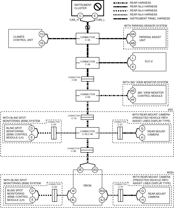
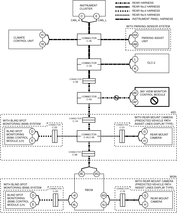
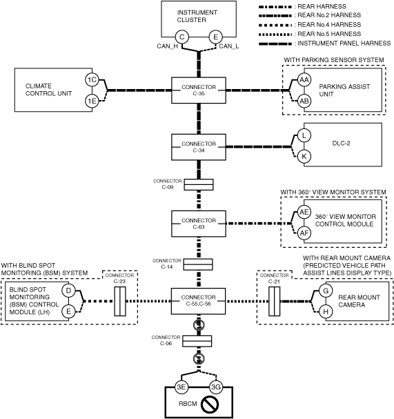
System wiring diagram
Inspection item
-
• Instrument cluster power supply voltage-related wiring harness and fuse
• Instrument cluster body ground related wiring harness
• Connector C-35
• Wiring harness between instrument cluster terminal C and connector C-35
• Wiring harness between instrument cluster terminal E and connector C-35
• Instrument cluster
B
Possible cause
-
• Connector terminal disconnection, poor contact, damage, deformation, corrosion
• Climate control unit power supply voltage or body ground malfunction
• Open circuit in wiring harness between climate control unit and connector C-35
• Connector C-35 malfunction
• Climate control unit malfunction
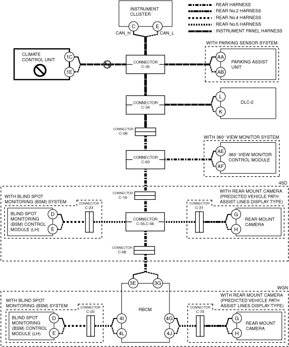
System wiring diagram
Inspection item
-
• Climate control unit power supply voltage-related wiring harness and fuse
• Climate control unit body ground related wiring harness
• Climate control unit connector
• Connector C-35
• Wiring harness between climate control unit 1C and connector C-35
• Wiring harness between climate control unit 1E and connector C-35
• Climate control unit
C
Possible cause
-
• Connector terminal disconnection, poor contact, damage, deformation, corrosion
• Parking assist unit power supply voltage or body ground malfunction
• Open circuit in wiring harness between parking assist unit and connector C-35
• Connector C-35 malfunction
• Parking assist unit malfunction
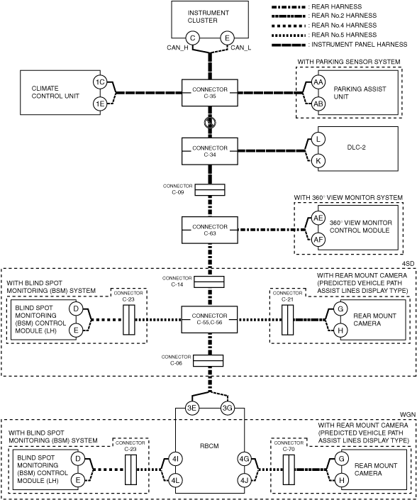
System wiring diagram
Inspection item
-
• Parking assist unit power supply voltage-related wiring harness and fuse
• Parking assist unit body ground related wiring harness
• Connector C-35
• Wiring harness between parking assist unit terminal AA and connector C-35
• Wiring harness between parking assist unit terminal AB and connector C-35
• Parking assist unit
D
Possible cause
-
• Connector terminal disconnection, poor contact, damage, deformation, corrosion
• Open circuit in wiring harness between connector C-35 and connector C-34
• Connector C-35 malfunction
• Connector C-34 malfunction
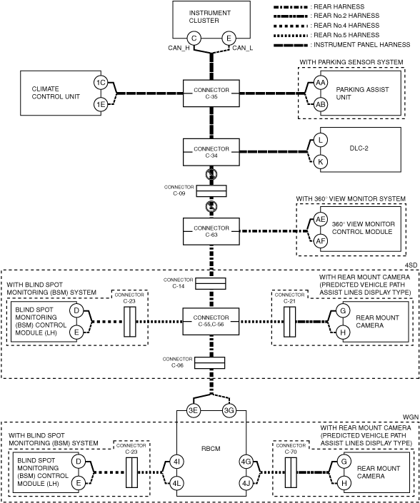
System wiring diagram
Inspection item
-
• Connector C-35
• Connector C-34
• Wiring harness between connector C-35 and connector C-34
E
Possible cause
-
• Connector terminal disconnection, poor contact, damage, deformation, corrosion
• Open circuit in wiring harness between connector C-34 and connector C-09
• Open circuit in wiring harness between connector C-09 and connector C-63
• Connector C-34 malfunction
• Connector C-09 malfunction
• Connector C-63 malfunction
System wiring diagram
Inspection item
-
• Connector C-34
• Connector C-09
• Connector C-63
• Wiring harness between connector C-34 and connector C-09
• Wiring harness between connector C-09 and connector C-63
F
Possible cause
-
• Connector terminal disconnection, poor contact, damage, deformation, corrosion
• 360° view monitor control module power supply voltage or body ground malfunction
• Open circuit in wiring harness between 360° view monitor control module and connector C-63
• Connector C-63 malfunction
• 360° view monitor control module malfunction
System wiring diagram
Inspection item
-
• 360° view monitor control module power supply voltage-related wiring harness and fuse
• 360° view monitor control module body ground related wiring harness
• Connector C-63
• Wiring harness between 360° view monitor control module terminal AE and connector C-63
• Wiring harness between 360° view monitor control module terminal AF and connector C-63
• 360° view monitor control module
G
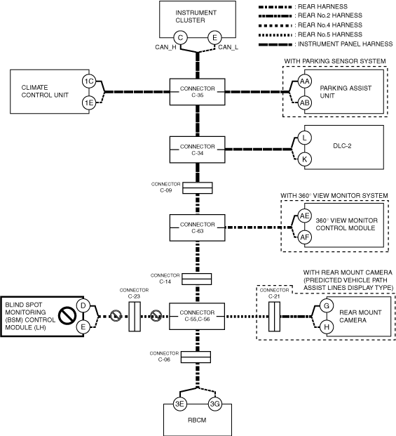
With 4SD
-
Possible cause
-
• Connector terminal disconnection, poor contact, damage, deformation, corrosion
• Open circuit in wiring harness between connector C-63 and connector C-14
• Open circuit in wiring harness between connector C-14 and connectors C-55,C-56
• Connector C-63 malfunction
• Connector C-14 malfunction
• Connectors C-55,C-56 malfunction
System wiring diagram
-
Inspection item
-
• Connector C-63
• Connector C-14
• Connectors C-55,C-56
• Wiring harness between connector C-63 and connector C-14
• Wiring harness between connector C-14 and connectors C-55,C-56
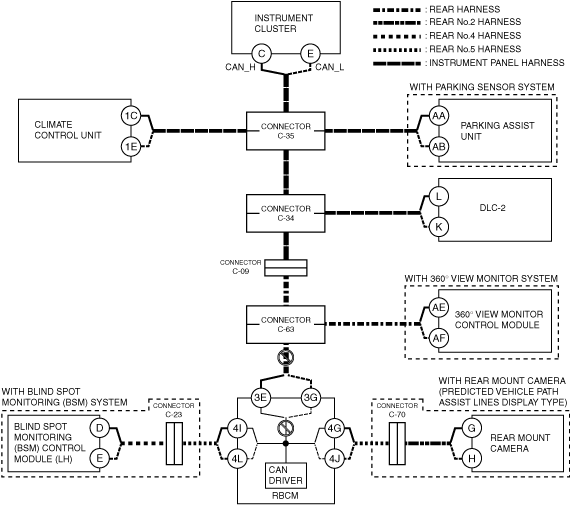
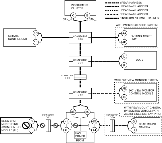
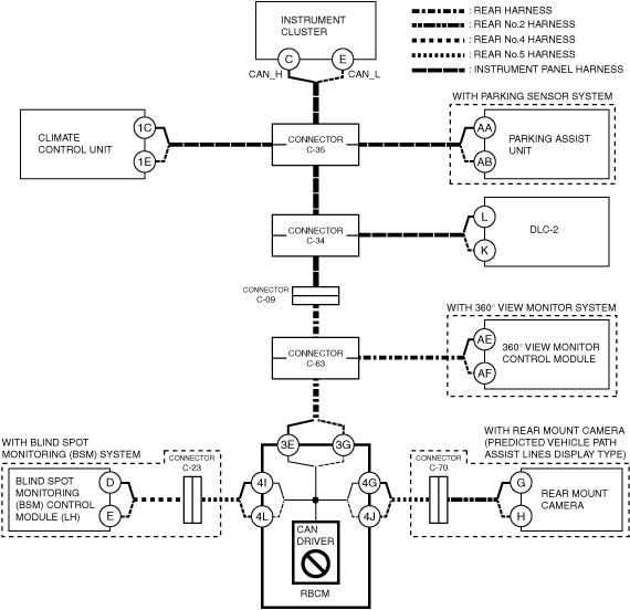
With WGN
-
Possible cause
-
• Connector terminal disconnection, poor contact, damage, deformation, corrosion
• Open circuit in wiring harness between connector C-63 and rear body control module (RBCM)
• Connector C-63 malfunction
• CAN circuit in rear body control module (RBCM) malfunction
System wiring diagram
-
Inspection item
-
• Connector C-63
• Rear body control module (RBCM) connector
• Wiring harness between rear body control module (RBCM) terminal 3E and connector C-63
• Wiring harness between rear body control module (RBCM) terminal 3G and connector C-63
• Rear body control module (RBCM)
-
― Between rear body control module (RBCM) terminal 3E and rear body control module (RBCM) terminal 4I or rear body control module (RBCM) terminal 4J
― Between rear body control module (RBCM) terminal 3G and rear body control module (RBCM) terminal 4L or rear body control module (RBCM) terminal 4G
H
With 4SD
-
Possible cause
-
• Connector terminal disconnection, poor contact, damage, deformation, corrosion
• Blind spot monitoring (BSM) control module (LH) power supply voltage or body ground malfunction
• Open circuit in wiring harness between blind spot monitoring (BSM) control module (LH) and connector C-23
• Open circuit in wiring harness between connector C-23 and connectors C-55,C-56
• Connector C-23 malfunction
• connectors C-55,C-56 malfunction
• Blind spot monitoring (BSM) control module (LH) malfunction
System wiring diagram
-
Inspection item
-
• Blind spot monitoring (BSM) control module (LH) power supply voltage-related wiring harness and fuse
• Blind spot monitoring (BSM) control module (LH) body ground related wiring harness
• Blind spot monitoring (BSM) control module (LH) connector
• Connector C-23
• Connectors C-55,C-56
• Wiring harness between connector C-23 and connectors C-55,C-56
• Wiring harness between blind spot monitoring (BSM) control module (LH) terminal D and connector C-23
• Wiring harness between blind spot monitoring (BSM) control module (LH) terminal E and connector C-23
• Blind spot monitoring (BSM) control module (LH)
With WGN
-
Possible cause
-
• Connector terminal disconnection, poor contact, damage, deformation, corrosion
• Blind spot monitoring (BSM) control module (LH) power supply voltage or body ground malfunction
• Open circuit in wiring harness between blind spot monitoring (BSM) control module (LH) and connector C-23
• Open circuit in wiring harness between connector C-23 and rear body control module (RBCM)
• Connector C-23 malfunction
• Blind spot monitoring (BSM) control module (LH) malfunction
• CAN circuit in rear body control module (RBCM) malfunction
System wiring diagram
-
Inspection item
-
• Blind spot monitoring (BSM) control module (LH) power supply voltage-related wiring harness and fuse
• Blind spot monitoring (BSM) control module (LH) body ground related wiring harness
• Blind spot monitoring (BSM) control module (LH) connector
• Rear body control module (RBCM) connector
• Connector C-23
• Wiring harness between blind spot monitoring (BSM) control module (LH) terminal D and connector C-23
• Wiring harness between blind spot monitoring (BSM) control module (LH) terminal E and connector C-23
• Wiring harness between connector C-23 and rear body control module (RBCM) terminal 4I
• Wiring harness between connector C-23 and rear body control module (RBCM) terminal 4L
• Rear body control module (RBCM)
-
― Between rear body control module (RBCM) terminal 3E and rear body control module (RBCM) terminal 4I
― Between rear body control module (RBCM) terminal 3G and rear body control module (RBCM) terminal 4L
• Blind spot monitoring (BSM) control module (LH)
I
With 4SD
-
Possible cause
-
• Connector terminal disconnection, poor contact, damage, deformation, corrosion
• Rear body control module (RBCM) power supply voltage or body ground malfunction
• Open circuit in wiring harness between connectors C-55,C-56 and connector C-06
• Open circuit in wiring harness between connector C-06 and rear body control module (RBCM)
• Connectors C-55,C-56 malfunction
• Connector C-06 malfunction
• Rear body control module (RBCM) malfunction
System wiring diagram
-
Inspection item
-
• Rear body control module (RBCM) power supply voltage-related wiring harness and fuse
• Rear body control module (RBCM) body ground related wiring harness
• Rear body control module (RBCM) connector
• Connectors C-55,C-56
• Connector C-06
• Wiring harness between connectors C-55,C-56 and connector C-06
• Wiring harness between connector C-06 and rear body control module (RBCM)
• Rear body control module (RBCM)
With WGN
-
Possible cause
-
• Connector terminal disconnection, poor contact, damage, deformation, corrosion
• Rear body control module (RBCM) power supply voltage or body ground malfunction
• Rear body control module (RBCM) malfunction
System wiring diagram
-
Inspection item
-
• Rear body control module (RBCM) power supply voltage-related wiring harness and fuse
• Rear body control module (RBCM) body ground related wiring harness
• Rear body control module (RBCM)