|
am6zzw00007209
FRONT OIL SEAL REPLACEMENT [L3 Turbo]
id0110b3800800
1. Disconnect the negative battery cable.
2. Remove the front tire (RH).
3. Remove the under cover.
4. Remove the splash shield (RH).
5. Remove the charge air cooler. (SeeINTAKE-AIR SYSTEM REMOVAL/INSTALLATION [L3 Turbo].)
6. Remove the high pressure fuel pump. (See HIGH PRESSURE FUEL PUMP REMOVAL/INSTALLATION [L3 Turbo].)
7. Remove the ignition coils. (See IGNITION COIL REMOVAL/INSTALLATION [L8, LF, L3, L3 Turbo].)
8. Disconnect the OCV connectors.
9. Disconnect the CMP sensor connector.
10. Disconnect the P/S oil pump connector.
11. Remove the ventilation hose.
12. Remove cylinder head cover. (See TIMING CHAIN REMOVAL/INSTALLATION [L3 Turbo].)
13. Remove the drive belt. (See DRIVE BELT REPLACEMENT [L3 Turbo].)
14. Remove the CKP sensor. (See CRANKSHAFT POSITION (CKP) SENSOR REMOVAL/INSTALLATION [L3 Turbo].)
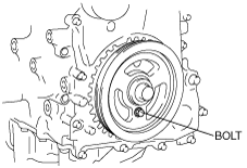
15. Remove in the order indicated in the figure.
16. Install in the reverse order of removal.
17. Bleed the air from the cooling system. (SeeENGINE COOLANT REPLACEMENT [L8, LF, L3, L3 Turbo].)
am6zzw00007209
|
|
1
|
Crankshaft pulley lock bolt
|
|
2
|
Crankshaft pulley
|
|
3
|
Front oil seal
(See Front Oil Seal Removal Note.)
|
Crankshaft Pulley Lock Bolt Removal Note
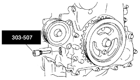
1. Remove the cylinder block lower blind plug and install the SST.
am6zzw00007210
|
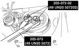
2. Verify that cylinder No.1 is at TDC of the compression stroke. (Position crank weight contacts SST.)
3. Install the SSTs to the crankshaft pulley and lock the crankshaft against rotation.
am6zzw00007211
|
Front Oil Seal Removal Note
1. Remove the oil seal lip using a razor.
2. Remove the oil seal using a flathead screwdriver with the tip protected by a rag to prevent crankshaft oil seal damage.
am6zzw00007212
|
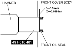
Front Oil Seal Installation Note
1. Apply clean engine oil to a new oil seal.
2. Insert the oil seal into the engine front cover.
3. Tap in the oil seal using the SST.
am6zzw00007213
|
am6zzw00007214
|
Crankshaft Pulley Lock Bolt Installation Note
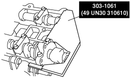
1. Install the SST to the camshaft as shown in the figure.
am6zzw00007215
|
2. Verify that cylinder No.1 is at TDC of the compression stroke. (Position crank weight contacts SST.)
3. To position the crankshaft pulley, temporarily tighten it and, using a suitable bolt (M6 x 1.0), fix the crankshaft pulley to the engine front cover.
am6zzw00007216
|
4. Install the SSTs to the crankshaft pulley and lock the crankshaft against rotation, and tighten the crankshaft pulley lock bolt using the following two steps.
am6zzw00007211
|
5. Remove the crankshaft pulley installation bolt (M6 X 1.0).
6. Remove the SST from the camshaft.
7. Remove the SST installed in the cylinder block lower blind plug hole.
8. Rotate the crankshaft clockwise two turns and inspect the valve timing.
9. Install the cylinder block lower blind plug.
am6zzw00007217
|