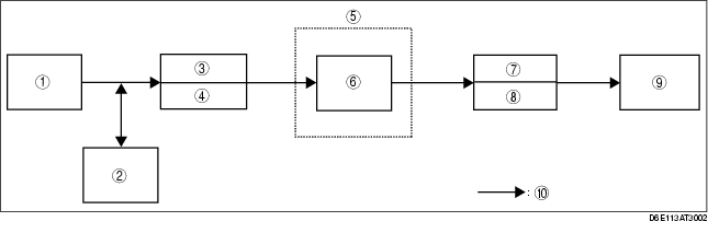
INTAKE-AIR SYSTEM FLOW DIAGRAM [L8, LF, L3]
id0113z1102200
.
1
Fresh-air duct
2
Resonance chamber
3
Air cleaner
4
VAD shutter valve (L3)
5
Throttle body
6
Throttle valve
7
Intake manifold
8
Variable intake air shutter valve (LF, L3)
9
Combustion chambers
10
Intake air flow