|
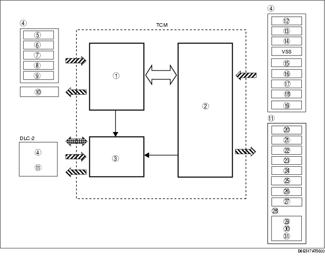
1
|
Engine control system
|
|
2
|
Transaxle control system
|
|
3
|
On-board diagnostic system
|
|
4
|
Input signals
|
|
5
|
MAF sensor
|
|
6
|
APP sensor
|
|
7
|
CKP sensor
|
|
8
|
Brake switch
|
|
9
|
ECT sensor
|
|
10
|
Engine control output signals
|
|
11
|
Output signals
|
|
12
|
TR switch
|
|
13
|
TFT sensor
|
|
14
|
Input/turbine speed sensor
|
|
15
|
Intermediate sensor
|
|
16
|
M range switch
|
|
17
|
Up switch
|
|
18
|
Down switch
|
|
19
|
Oil pressure switch
|
|
20
|
Pressure control solenoid A
|
|
21
|
Pressure control solenoid B
|
|
22
|
Shift solenoid A
|
|
23
|
Shift solenoid B
|
|
24
|
Shift solenoid C
|
|
25
|
Shift solenoid D
|
|
26
|
Shift solenoid E
|
|
27
|
Shift solenoid F
|
|
28
|
Instrument cluster
|
|
29
|
Gear position indicator light
|
|
30
|
AT warning light
|
|
31
|
Selector indicator light
|