FOREWORD [WATER HEATER SYSTEM]
id070200820128
Outline
• When the customer reports a vehicle malfunction, verify the DTC, then diagnose the malfunction according to following flowchart.
-
- If a DTC exists, diagnose according to the applicable DTC inspection (See DTC Table (Water Heater System).)
-
- If a DTC exists, diagnose according to the applicable symptom troubleshooting (See TROUBLESHOOTING INDEX.)

Read/clear diagnostic results
-
• This function allows you to read or clear DTCs in the water heater unit.
DTCs Reading Procedure
1. Perform the necessary vehicle preparation and visual inspection.
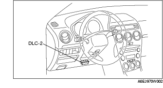
2. Connect SST (WDS or equivalent) to the vehicle DLC-2 16-pin connector located as shown in the figure.
3. Retrieve DTCs using WDS or equivalent.
KOEO Self Test/Combustion Test
1. Connect the SST (WDS or equivalent) to the vehicle DLC-2 16-pin connector located as shown in the figure.
2. Select the "Supplemental Heater Test" in the "Supplemental Heater Menu" of the "Guided Diagnosis" function.
3. Perform the KOEO Self Test/Combustion Test.
-
Note
-
• If the water heater unit is operating, the water heater unit will reject the test command. Perform the DTC reading procedure after the water heater unit stops operating.
After Repair Procedure
1. Connect the SST (WDS or equivalent) to the vehicle DLC-2 16-pin connector located as shown in the figure.
2. Turn the ignition switch to the ON position.
3. Perform the DTCs reading procedure and record any DTCs that are retrieved.
4. Clear the DTCs using the SST (WDS or equivalent).
5. Verify that the customer's concern has been resolved.
Lockout Reset
Using the SST (WDS or equivalent)
1. Connect the SST (WDS or equivalent) to the vehicle DLC-2 16-pin connector located as shown in the figure.
2. Select "CLR_LOCKOUT" and "LOCKOUT".
3. Turn "CLR_LOCKOUT" to ON using the simulation function.
4. Verify that the "LOCKOUT" reading changes to "Unlocked".
Not using the SST (WDS or equivalent)
For factory equipped water heater unit
-
1. Turn the ignition switch to the OFF position.

-
2. Remove the HEATER 20 A fuse from the main fuse block for more than 5 s.
-
3. Re-install the HEATER 20 A fuse.
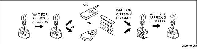
For vehicles with a transmitter or timer
-
1. Turn the ignition switch to the OFF position.
-
2. Remove the power supply 20 A fuse from the heater wiring harness for approx. 3 s.
-
3. Re-install the power supply 20 A fuse.
-
4. Press and hold down the ON switch of the transmitter or timer for approx. 3 s.
-
5. Remove the power supply 20 A fuse from the heater wiring harness for approx. 3 s.
-
6. Re-install the power supply 20 A fuse.
PID/Data Monitor and Record Procedure
1. Connect SST (WDS or equivalent) to the vehicle DLC-2 16-pin connector located as shown in the figure.
2. Access and monitor PIDs by WDS or equivalent.