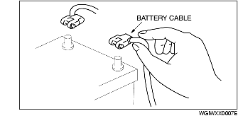
• Before disconnecting connectors or removing electrical parts, disconnect the negative battery cable.
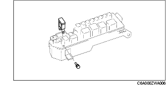
• To remove the wiring harness from the clip in the engine room, pry up the hook of the clip using a flathead screwdriver.
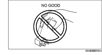
• When disconnecting connector, grasp the connectors, not the wires.

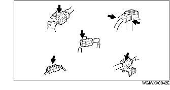
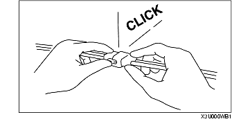
• Connectors can be disconnected by pressing or pulling the lock lever as shown.
• When locking connectors, listen for a click indicating they are securely locked.
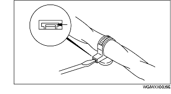
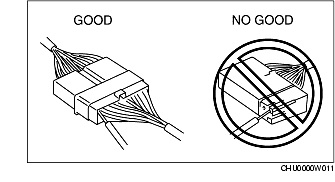
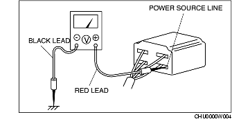
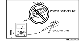
• When a tester is used to inspect for continuity or measuring voltage, insert the tester probe from the wiring harness side.
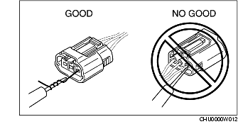
• Inspect the terminals of waterproof connectors from the connector side since they cannot be accessed from the wiring harness side.
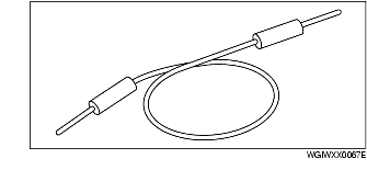
• Pull lightly on individual wires to verify that they are secured in the terminal.

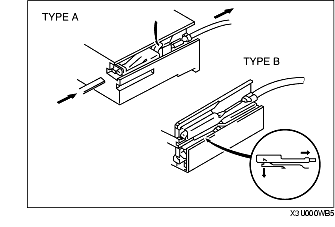
• Use the appropriate tools to remove a terminal as shown. When installing a terminal, be sure to insert it until it locks securely.
• Insert a thin piece of metal from the terminal side of the connector and with the terminal locking tab pressed down, pull the terminal out from the connector.
• Handle sensors, switches, and relays carefully. Do not drop them or strike them against other objects.
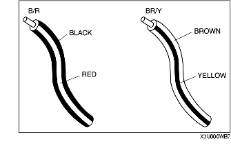
• Two-color wires are indicated by a two-color code symbol.
• The first letter indicates the base color of the wire and the second the color of the stripe.
|
CODE
|
COLOR
|
CODE
|
COLOR
|
|---|---|---|---|
|
B
|
Black
|
O
|
Orange
|
|
BR
|
Brown
|
P
|
Pink
|
|
G
|
Green
|
R
|
Red
|
|
GY
|
Gray
|
V
|
Violet
|
|
L
|
Blue
|
W
|
White
|
|
LB
|
Light Blue
|
Y
|
Yellow
|
|
LG
|
Light Green
|
-
|
-
|
• When replacing a fuse, be sure to replace it with one of the same capacity. If a fuse fails again, the circuit probably has a short and the wiring should be inspected.
• Be sure the negative battery terminal is disconnected before replacing a main fuse.
• When replacing a pullout fuse, use the fuse puller.

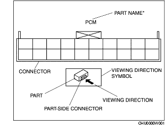
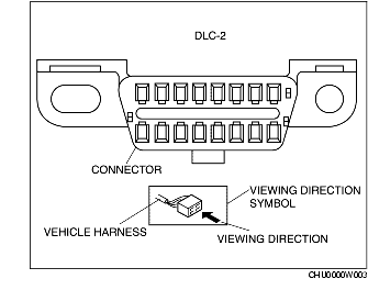
• The viewing direction of connectors is indicated with a symbol.
• The figures showing the viewing direction are the same as those used in Wiring Diagrams.
• The viewing directions are shown in the following three ways:
The viewing direction of part-side connectors is from the terminal side.
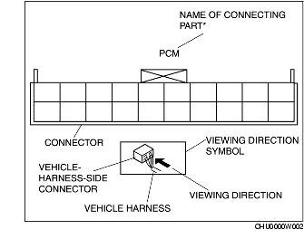
The viewing direction of vehicle harness-side connectors is from the harness side.
When it is necessary to show the terminal side of vehicle harness-side connectors, such as the following connectors, the viewing direction is from the terminal side.
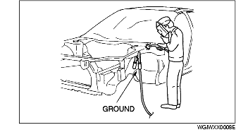
A vehicle has various electrical parts. To protect the parts from excessive current generated when welding, be sure to perform the following procedure.
1. Turn the ignition switch to the LOCK position.
2. Disconnect the battery cables.
3. Securely connect the welding machine ground near the welding area.
4. Cover the peripheral parts of the welding area to protect them from weld spatter.