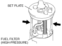
FUEL PUMP UNIT DISASSEMBLY/ASSEMBLY [LF, L3]
id0114008010a4
-
Warning
-
• Fuel line spills and leakage are dangerous. Fuel can ignite and cause serious injuries or death and damage. Fuel can also irritate skin and eyes. To prevent this, do not damage the sealing surface of the fuel pump unit when removing or installing.
-
Caution
-
• Do not touch the fuel pump discharge pipe unless it is necessary. If servicing is needed, be careful not to damage the pipe with tools or other objects, or by applying lateral stress. If the pipe is damaged, it may cause fuel leakage or a fuel pump operation malfunction.
• Be careful not to damage the pressure regulator or fuel hose. If it is damaged, it may cause fuel leakage.
• When any parts are removed, be careful that no foreign materials penetrate the part. Otherwise it may cause a fuel pump unit operation malfunction.
• Protect any removed parts using rubber matting to prevent damage. Furthermore, if a part has been dropped, do not reuse it, replace it with a new one.
• Do not use any textile products such as cotton work gloves. If used, fabric may get caught in the fuel pump or pressure regulator causing a fuel pump unit operation malfunction.
• Do not touch the flange seal side of the set plate. If it is damaged or foreign material adheres, it may cause fuel leakage.
• When removing foreign material inside the reserve cup, use fuel for flushing. If foreign material is removed with air, it may penetrate into the jet pump pressure regulator.
-
Note
-
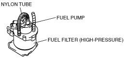
• The disassembly/assembly procedure differs depending on whether the nylon tube between the fuel filter (high-pressure) and fuel pump is equipped or not, or if the fuel filter (high-pressure) and fuel pump are replaced as a single unit or replaced separately.
|
Specification
|
With nylon tube
|
Without nylon tube
|
|
single unit
|
separately
|
|
2WD
|
4WD
|
2WD
|
4WD
|
2WD
|
4WD
|
|
Type
|
A
|
—
|
B
|
C
|
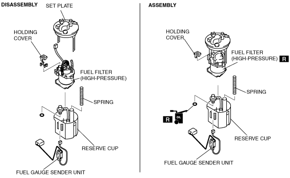
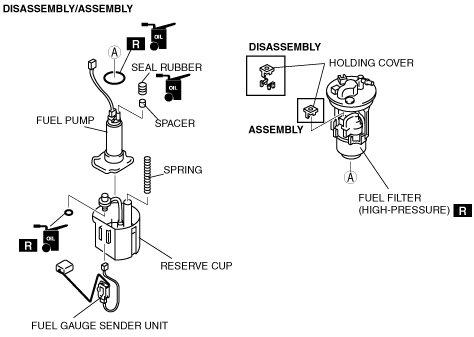
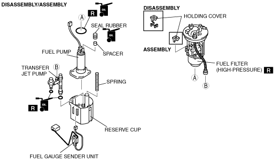
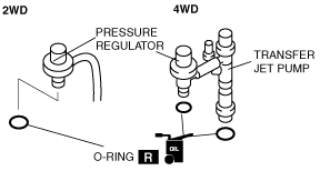
Type A; With nylon tube, replaced as a single unit (2WD)
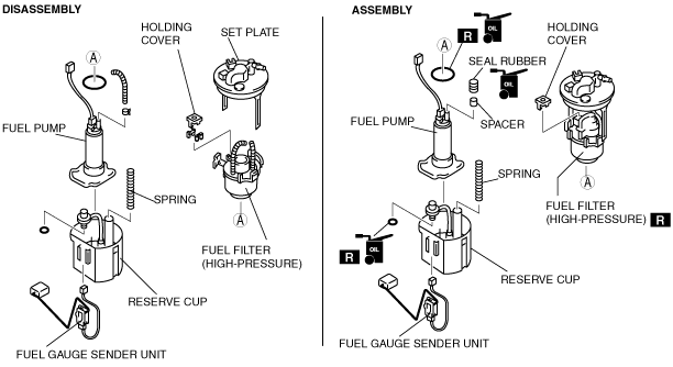
Type B; With nylon tube, replaced separately (2WD)
Type B; With nylon tube, replaced separately (4WD)
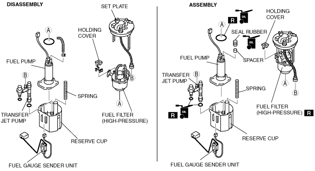
Type C; Without nylon tube (2WD)
Type C; Without nylon tube (4WD)
Disassembly
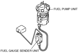
1. Remove the fuel gauge sender unit.
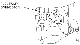
2. Disconnect the fuel pump connector.
3. Remove the arm part of the set plate.
-
Note
-
• The disassembly procedure differs depending on whether the nylon tube between the fuel filter (high-pressure) and fuel pump is equipped or not.
• Perform Step 4 (typeA, B).
Type A, B
-
Caution
-
• Cut the nylon tube at the center. If it is cut at both ends, it may cause pipe damage.
4. Cut the center part of the nylon tube located between the fuel filter (high-pressure) and set plate.
Type A, B, C
-
Note
-
• Perform Step 5 (4WD).
• Go to Step 6 (2WD).
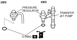
5. Disconnect the quick release connector from the transfer jet pump (4WD).
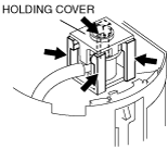
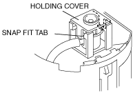
6. Cut the four legs located under the pressure regulator holding cover.
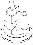
7. Remove the holding cover from the pressure regulator.
-
Caution
-
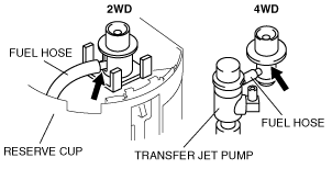
• Do not pull out the fuel hose located between the pressure regulator and reserve cup (2WD) or between the pressure regulator and transfer jet pump (4WD). Do not forcedly rotate or bend it, or it could damage the sealing of the fuel hose (press fit area), or cause pipe breakage or splitting. In addition, if the fuel hose is buckled and fuel flow distortion occurs, it may cause jet pump performance deterioration.
-
Note
-
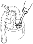
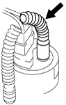
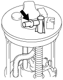
• Inserting the tip of the flathead screwdriver into the position indicated in the figure and rotating it clockwise could make it easier to remove the pressure regulator.
8. Remove the pressure regulator from the fuel filter (high-pressure).
-
Note
-
• Perform Step 9 (4WD).
• Go to Step 10 (2WD).
• After removing the fuel filter (high-pressure) from the reserve cup, remove the transfer jet pump completely (4WD).
9. Remove the transfer jet pump from the reserve cup, and position of the way (4WD).
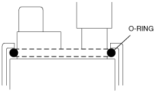
10. Remove the O-ring from the pressure regulator and replace with a new one.
-
Caution
-
• Be careful not to apply excessive pressure to the reserve cup. Applying excessive pressure may cause splitting, chipping, or bending.
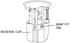
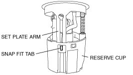
11. Disengage the snap fit tab from the reserve cup using a flathead screwdriver.
12. Remove the fuel filter (high-pressure) and fuel pump as a single unit from the reserve cup.
13. Verify that the reserve cup is not split, chipped, or bent.
-
Note
-
• Perform Step 14 (4WD).
• Go to the Step 15 (2WD).
14. Remove the O-ring from the transfer jet pump and replace with a new one (4WD).
-
Note
-
• The disassembly procedure differs depending on whether the nylon tube between the fuel filter (high-pressure) and fuel pump is equipped or not separately.
• Perform Step 15 (type B).
• Go to Step 23 (type A).
• Go to Step 19 (typeC).
Type B
-
Caution
-
• Cut the nylon tube in the center. If it is cut at the both ends, it may cause pipe damage.
15. Cut apart the nylon tube in the center part between the fuel filter (high-pressure) and fuel pump.
16. Insert the tip of a flathead screwdriver into the position shown in the figure and loosen the fuel pump discharge pipe clip by slowly moving it left and right.
17. Detach the clips.
-
Caution
-
• When removing the nylon tube, do not use a cutter knife or similar object. Otherwise, the fuel pump discharge pipe could be damaged, or fuel leakage may occur.
18. Remove the nylon tube from the fuel pump discharge pipe using pliers.
Type B, C
-
Caution
-
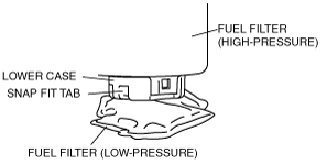
• Be careful not to apply excessive pressure to the lower case. Applying excessive pressure may cause splitting, chipping, or bending.
19. Disengage the snap fit tab of the lower case using a flathead screwdriver.
-
Caution
-
• Slowly remove the fuel pump being careful not to press the fuel pump discharge pipe or pull the fuel filter (low-pressure), or it may damage the discharge pipe or dislocate/tear the fuel filter (low-pressure).
20. Remove the fuel pump from the fuel filter (high-pressure).
21. Verify that lower case is not split, chipped, or bent.
22. Remove the O-ring from the fuel pump and replace it with a new one.
Type A, B, C
-
Caution
-
• Grasp the spring end on the set plate side and slowly remove it being careful not to stretch the spring. If the spring is stretched beyond its free length, changes in the fuel pump unit installation load may occur and cause damage to the reserve cup.
23. Remove the spring from the set plate.
Assembly
-
Note
-
• The assembly procedure differs depending on whether the fuel filter (high-pressure) and fuel pump are replaced as a single unit or replaced separately.
• Perform Step 1 (type B, C).
• Go to Step 7 (type A).
Type B, C
-
Caution
-
• Be careful not to damage the O-ring or seal rubber. If it is damaged, a seal malfunction may occur causing a fuel leakage.
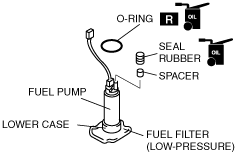
1. Apply clean oil to the new O-ring and seal rubber.
2. Install the O-ring in the position shown in the figure for the fuel pump, being careful not to twist it.
3. Install the spacer and seal rubber to the fuel pump discharge pipe. Verify that the lower case is not split, chipped, or bent.
-
Caution
-
• Hold the fuel pump in the upright position and insert it from the bottom side, being careful not to apply load to the fuel filter (low-pressure). If load is applied to the fuel filter (low-pressure), it may cause the filter to dislocate or tear.
• Install the O-ring in the upright position. If it is not in the upright position, fuel pump vibration may be transmitted to the fuel filter (high-pressure) causing noise inside the vehicle.
4. Hold the fuel pump in the upright position and insert it into the fuel filter from the bottom side being careful not to twist the O-ring.
5. Engage the snap fit tab and lower case, and verify that they are properly engaged.
6. Verify that the O-ring is seated in the upright position without twisting.
Type A, B, C
-
Caution
-
• Be careful not to damage the O-ring. If it is damaged, sealing damage might occur causing fuel leakage.
7. Apply clean oil to the new O-ring.
-
Caution
-
• Do not pull out the fuel hose between the pressure regulator and reserve cup (2WD) or between the pressure regulator and transfer jet pump (4WD). In addition, do not forcibly rotate or bend it, or it may cause damage to the fuel hose sealing or pipe breakage/splitting. If the fuel hose is buckled and fuel flow distortion occurs, it may cause jet pump performance deterioration.
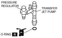
8. Install a new O-ring to the pressure regulator.
-
Note
-
• Perform Step 9 (4WD).
• Go to Step 11 (2WD).
9. Install a new O-ring to the transfer jet pump (4WD).
-
Note
-
• After installing the fuel filter (high-pressure) to the reserve cup, install the transfer jet pump completely (4WD).
10. Set the transfer jet pump to the reserve cup (4WD).
11. Verify that the reserve cup is not split, chipped, or bent.
12. Install the fuel filter (high-pressure) to the reserve cup.
13. Engage the snap fit tab and reserve cup, and verify that they are properly engaged.
-
Note
-
• Perform Step 14 (2WD).
• Go to Step 15 (4WD).
14. Install the pressure regulator to the fuel filter (high-pressure) (2WD).
-
Note
-
• Perform Step 15 (4WD).
• Go to Step 16 (2WD).
15. Install the transfer jet pump to the reserve cup and pressure regulator to the fuel filter (high-pressure) together at the same time (4WD).
16. Install the pressure regulator holding cover and verify that the snap fit tab is properly engaged.
-
Note
-
• Perform Step 17 (4WD).
• Go to Step 18 (2WD).
17. Connect the quick release connector to the transfer jet pump (4WD).
-
Caution
-
• Grasp the spring end on the set plate side and slowly install it without rotating. If it is rotated, the rubber might wear out.
18. Install the spring to the set plate.
-
Caution
-
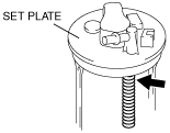
• Do not grasp the pipe located on the upper surface of the set plate. The pipe may be damaged causing fuel leakage.
19. Perform the following procedure to install the set plate to the reserve cup.
- (1) Position the fuel gauge sender unit installation side of the reserve cup outward.
- (2) Rotate the set plate 90° counter-clockwise viewing the set plate from above.
-
-
Caution
-
• Be careful not to break the set plate arm by applying excessive pressure. If it is broken, it may cause a fuel pump unit operation malfunction.
- (3) Insert the set plate arm to the reserve cup.
- (4) Engage the snap fit tab and set plate arm, and verify that they are properly engaged.
-
20. Install the fuel gauge sender unit.
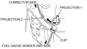
21. Perform the following procedure to connect the fuel gauge sender unit connector, routing the wiring harness in the proper position.
- (1) Install the wiring harness to the reserve cup clip.
-
- (2) Wrap the wiring harness around projection 1 so that connector-side wiring harness is routed underside.
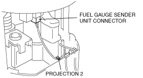
- (3) Route the wiring harness under projection 2.
-
- (4) Connect the connector.
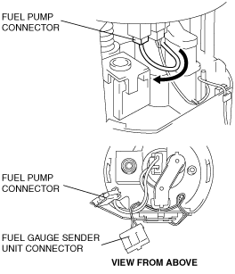
22. Perform the following procedure to connect the fuel pump connector, routing the wiring harness in the proper position.
- (1) Position the fuel gauge sender unit installation surface outward.
- (2) Remove the fuel pump connector wiring harness from the right side of the fuel gauge sender unit connector.
-
- (3) Connect the connector.
23. Press the set plate to expand/contract the fuel pump unit, and inspect it for the following:
-
• The fuel gauge sender unit connector wiring harness does not depart from the clip or projection.
• The fuel gauge sender unit connector wiring harness is not pulled. The fuel pump connector wiring harness is not pinched into the pressure regulator holding cover.
24. Inspect the following and verify that each part is normal.
-
• Resistance inspection of fuel gauge sender unit
• Missing part
• Engagement condition of snap fit areas
• Splitting, chipping, bending, and cracking in each part
• Wiring harness routing
• Connector condition