 |
am6zzw00005367
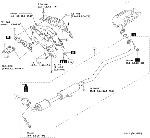
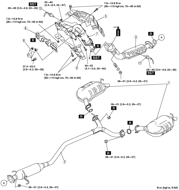
EXHAUST SYSTEM REMOVAL/INSTALLATION [LF, L3]
id0115008002c2
1. Disconnect the negative battery cable.
2. Remove the plug hole plate. (See PLUG HOLE PLATE REMOVAL/INSTALLATION [L3].)
3. Remove in the order indicated in the table.
4. Install in the reverse order of removal.
Unleaded fuel model
am6zzw00005367
|
|
1
|
Main silencer
|
|
2
|
Middle pipe
|
|
3
|
TWC
|
|
4
|
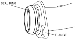
Seal ring
(See Seal Ring Removal Note.)
(See Seal Ring Installation Note.)
|
|
5
|
Exhaust manifold insulator (upper)
|
|
6
|
Bracket
|
|
7
|
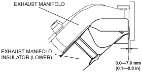
Exhaust manifold
|
|
8
|
Exhaust manifold gasket
|
|
9
|
Exhaust manifold insulator (lower)
|
|
10
|
HO2S (front)
(See HO2S Removal Note)
|
|
11
|
HO2S (rear)
(See HO2S Removal Note)
|
Leaded fuel model
am6zzw00005368
|
|
1
|
Main silencer
|
|
2
|
Presilencer
|
|
3
|
Seal ring
(See Seal Ring Removal Note.)
(See Seal Ring Installation Note.)
|
|
4
|
Exhaust manifold insulator (upper)
|
|
5
|
Bracket
|
|
6
|
Exhaust manifold
|
|
7
|
Exhaust manifold gasket
|
|
8
|
Exhaust manifold insulator (lower)
|
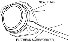
Seal Ring Removal Note
1. Remove the seal ring using a flathead screwdriver being careful not to damage the pipe.
am6zzw00005369
|
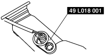
HO2S Removal Note
1. Remove the HO2S using the SST before removing the exhaust manifold.
am6zzw00005370
|
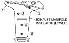
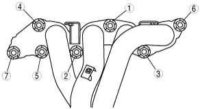
Exhaust Manifold Insulator (Lower) Installation Note
1. Tighten the exhaust manifold insulator (lower) installation bolts in the order shown.
a6a3914w003
|
2. Verify that the insulator is installed as shown.
a6a3914w004
|
Exhaust Manifold Installation Note
1. Tighten the exhaust manifold installation nuts in the order shown.
a6e3914w003
|
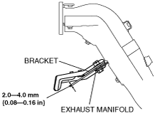
Bracket Installation Note
1. Temporarily tighten the exhaust manifold side bolts.
2. Verify that the gap between the exhaust manifold and the bracket is 2.0—4.0 mm {0.08—0.16 in}.
a6a3914w005
|
3. Fully tighten the cylinder block side bolt.
4. Fully tighten the exhaust manifold side bolts.
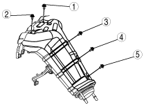
Exhaust Manifold Insulator (Upper) Installation Note
1. Tighten the exhaust manifold insulator (upper) installation bolts in the order shown.
a6a3914w006
|
Seal Ring Installation Note
1. Temporarily install the seal ring to the pipe so that the seal ring is even with the flange.
am6zzw00005371
|
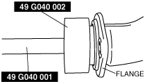
2. Install the SST to the seal ring so that the SST is even with the flange.
am6zzw00005372
|
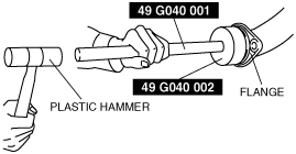
3. Press in the seal ring by tapping the SST using a plastic hammer until the seal ring contacts the flange.
am6zzw00005373
|
TWC, Presilencer Installation Note
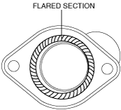
1. Spray carbon remover (TB6601 or equivalent) on the flared section of the exhaust pipe.
am6zzw00002918
|
2. Remove the carbon adhering to the flared section shown in the figure using a nylon brush or sandpaper (No. 400 or equivalent).
3. Apply 1.0—2.5 g {0.036—0.088 oz} of grease (L3Z5 40 589) along the perimeter of the flared section.