Diagnostic procedure
|
STEP
|
INSPECTION
|
ACTION
|
|
|---|---|---|---|
|
1
|
INSPECT ABS FUSE CONDITION
• Is ABS fuse (60 A) okay?
|
Yes
|
Go to next step.
|
|
No
|
Replace fuse, then go to Step 4.
|
||
|
2
|
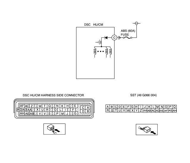
INSPECT FAIL-SAFE RELAY POWER SUPPLY CIRCUIT FOR OPEN CIRCUIT
• Turn ignition key to OFF.
• Disconnect DSC HU/CM connector.
• Connect SST (adapter harness) to DSC HU/CM connector (harness side only).
• Turn ignition key to ON (engine OFF).
• Measure voltage between DSC HU/CM terminal C (harness side) of SST and ground.
• Is voltage B+?
|
Yes
|
Go to next step.
|
|
No
|
Repair or replace harness for open circuit between battery positive terminal and DSC HU/CM terminal C, then go to Step 4.
|
||
|
4
|
VERIFY FAIL-SAFE OPERATION
• Turn ignition key to OFF.
• Remove SST (adapter harness) and connect all disconnected connectors.
• Connect WDS or equivalent to DLC-2.
• Turn ignition key to ON (engine OFF).
• Access ABS_POWER using WDS or equivalent.
• Does fail-safe relay operate?
|
Yes
|
Go to next step.
|
|
No
|
Replace DSC HU/CM, then go to next step.
|
||
|
5
|
VERIFY TROUBLESHOOTING COMPLETED
• Clear DTC from memory.
(See Clearing DTCs Procedures.)
• Is same DTC present?
|
Yes
|
Replace DSC HU/CM, then go to next step.
|
|
No
|
Go to next step.
|
||
|
6
|
VERIFY AFTER REPAIR PROCEDURE
• Is there any other DTC present?
|
Yes
|
Go to applicable DTC inspection.
|
|
No
|
Troubleshooting completed.
|
||