PRECAUTION
id040300804100
Vehicles with ABS/TCS
1. The ABS warning light, BRAKE system warning light, TCS indicator light and/or TCS OFF light illuminate even when the system is normal.
|
Warning lights that may illuminate and/or flash
|
Cases in which the light may illuminate
|
Conditions in which the light will go out
|
ABS, EBD and TCS control
|
|
Any or all the following light(s) illuminate:
• ABS warning light
• BRAKE system warning light(*1)
|
Under any of the following conditions:
• When the front wheels are jacked up, stuck, or placed on a chassis roller, and only the front wheel ABS wheel speed sensors are spun for more than 60 seconds.
|
After turning ignition switch OFF, vehicle is driven at speed greater than 10 km/h {6.2 mph} and normal operation is confirmed.
|
• ABS: Cuts control.
• EBD:
1. Cuts control, in cases where the light may illuminate, only when ABS CM detects that a wheel speed sensor determines that more than the two rear wheels are malfunctioning.
2. Operates control, if wheel speed sensor determines that more than 3 wheels are functioning correctly.
|
|
Parking brake is not fully released while driving.
|
|
Brake drag.
|
|
Sudden acceleration/deceleration.
|
|
Left/right or front/rear tires are different. (Size, radius, tire pressure, or wear is other than that listed on tire label.)
|
|
All the following lights illuminate:
• ABS warning light
• BRAKE system warning light
|
Battery voltage at ABS-TCS HU/CM ignition terminal Z drops below about 9 to 10 V.(*2)
|
Battery voltage rises above about 10 V.
(Only BRAKE system warning light goes out.)
|
ABS: Operates control.
EBD: Operates control.
|
-
*1 :
In cases where the light may illuminate, only when ABS/TCS HU/CM detects that a rear wheel`s speed sensor is malfunctioning.
-
*2 :
If battery voltage drops below 9 V while vehicle speed is greater than 6 km/h{3.7mph}, ABS HU/CM records DTC B1318.
|
Warning lights that may illuminate and/or flash
|
Cases in which the light may illuminate
|
Conditions in which the light will go out
|
ABS, EBD and TCS control
|
|
The following lights illuminate:
• TCS OFF light
|
When the engine coolant temperature is below 0°C {32°F}.(*1)
|
When engine is started and engine coolant temperature rises above 0°C {32°F}.)
|
ABS: Cuts control.
EBD: Cuts control.
TCS:
1. If TCS is operating, cuts control after gradually released TCS control value.
2. If TCS is not operating, cuts control.
|
|
All the following lights flash:
• ABS warning light
• BRAKE system warning light
• TCS OFF light
|
When confirming DTC,PID/DATA and ACTIVE COMAND MODES item using NGS tester.
|
When ABS ON-BOARD DIAGNOSTIC SYSTEM is released.
|
ABS: Cuts control.
EBD: Cuts control.
TCS: Cuts control.
|
|
The following light illuminates:
• TCS OFF light
|
For 1 second after starting the engine.
|
More than 1 second after starting the engine.
|
ABS: Cuts control.
EBD: Cuts control
TCS: Cuts control.
|
|
Warning lights that may illuminate and/or flash.
|
Cases in which the light may illuminate.
|
Conditions in which the light will go out.
|
ABS, EBD, TCS control.
|
-
*1 :
DTC U2021 for past malfunction is not recorded in the ABS/TCS HU/CM. DTC U2021 for present malfunction displayed, but goes out when engine coolant temperature rises above 0°C {32°F}.
2. Precautions during servicing of ABS/TCS
The ABS/TCS is composed of electrical and mechanical parts.It is necessary to categorize malfunctions as being either electrical or hydraulic when performing troubleshooting.
-
(1) Malfunctions in electrical system
-
• The ABS/TCS hydraulic unit and control module (ABS/TCS HU/CM) has an on-board diagnostic function. With this function, the ABS warning light and/or BRAKE system warning light will come on when there is a problem in the electrical system. Also, past and present malfunctions are recorded in the ABS/TCS HU/CM. This function can find malfunctions that do not occur during periodic inspections. Turn the ignition switch on by shorting the TBS terminal of the data link connector to body GND, or by connecting the SST, and approximately 5 seconds later the stored malfunctions will be displayed in the order of occurrence. To find out the causes of ABS/TCS malfunctions, use these on-board diagnostic results.
-
• If a malfunction occurred in the past but is now normal, the cause is likely a temporary poor connection of the harness. The ABS/TCS HU/CM usually operates normally. Be careful when searching for the cause of malfunction.
-
• After repair, it is necessary to clear the
-
DTC from the ABS/TCS HU/CM memory. Also, if the ABS/TCS related parts have been replaced, verify that the no DTC has been displayed after repairs.
-
• After repairing the ABS wheel-speed sensor or ABS sensor rotor, or after replacing the ABS CM (ABS motor or ABS motor relay or solenoid valve), the ABS warning light may not go off (*) even when the ignition switch is turned on. In this case, drive the vehicle at a speed of more than 10 km/h{6.2 mph}, make sure that ABS warning light goes off, and then clear the DTC.
-
* The BRAKE system warning light also illuminates when any rear wheel malformations.
-
• When repairing, if the ABS/TCS related connectors are disconnected and the ignition switch is turned on, the ABS/TCS CM will mistakenly detect a fault and record it as a malfunction.
-
• To protect the ABS/TCS HU/CM, make sure the ignition is off before connecting or disconnecting the ABS/TCS CM connector.
-
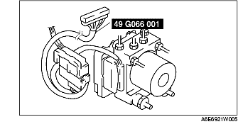
• To protect the terminal, use the SST(ABS/TCS: 49 G066 001, DSC: 49 G066 004) when connecting the tester lead to the ABS/TCS HU/CM connector.
-
(2) Malfunctions in hydraulic system
-
• Symptoms in a hydraulic system malfunction are similar to those in a conventional brake malfunction. However, it is necessary to determine if the malfunction is in an ABS component or the conventional brake system.
-
• The ABS hydraulic unit contains delicate mechanical parts. If foreign materials get into the component, the ABS may fail to operate. Also, it will likely become extremely difficult to find the location of the malfunction in the event that the brakes operate but the ABS does not. Make sure foreign materials do not get inside when servicing the ABS (e.g. brake fluid replacement, pipe removal).
Vehicle with DSC
1. The ABS warning light and/or BRAKE system warning light and/or DSC indicator light and/or TSC OFF light illuminate even when the system is normal.
|
Warning lights that may illuminate and/or flash
|
Cases in which the light may illuminate
|
Conditions in which the light will go out
|
ABS, EBD, TCS and DSC control
|
|
• ABS warning light
• BRAKE system warning light
• DSC indicator light
• TSC OFF light
|
Under any of the following conditions:
• When the front wheels are jacked up, struck, or placed on a chassis roller, and only the front wheel ABS wheel speed sensors are spun for more than 60 seconds.
|
After turning ignition switch OFF, vehicle is driven at speed greater than 10 km/h {6.2 MPH} and normal operation is confirmed.
|
• ABS: Cuts control.
• EBD: Cuts control.
• TCS: Cuts control.
• DSC: Cuts control.
|
|
Parking brake is not fully released while driving.
|
|
Brake drag.
|
|
Sudden
acceleration/deceleration.
|
|
Left/right or front/rear tires are different. (Size, radius, tire pressure, or wear is other than that listed on tire label.)
|
|
Battery voltage at DSC unit ignition terminal drops below about 9.5 V.
|
Battery voltage rises above about 9.5 V.
|
ABS: Operates control.
EBD: Operates control.
TCS: Operates control.
DSC: Operates control.
|
|
• Brake system warning light
• DSC indicator light
• TSC OFF light
|
Brake fluid amount is low.
|
Brake fluid level lower than recommended amount.
|
ABS: Operates control.
EBD: Operates control.
TCS: Cuts control.
DSC: Cuts control.
|
2. Precautions during servicing of DSC The DSC is composed of electrical and mechanical parts. It is necessary to categorize malfunctions as being either electrical or hydraulic when performing troubleshooting.
-
(1) Malfunction in electrical system
-
• The control module has an on-board diagnostic function. With this function, the ABS warning light and/or BRAKE system warning light and/or DSC indicator light and/or TSC OFF light will come on when there is a problem in the electrical system.
-
Also, past and present malfunctions are recorded in the control module. This function can find malfunctions that do not occur during periodic inspections. Short the TBS terminal of the data link connector to body GND or connect the WDS or equivalent to the DLC-2, then turn the ignition switch on. As a result, the stored malfunctions will be shown with ABS warning light on by shorting the TBS terminal, or displayed on the WDS or equivalent in numeric order by connecting DLC-2. To find out the causes of DSC malfunctions, use these on-board diagnostic results.
-
• If a malfunction occurred in the past but is now normal, the cause is likely a temporary poor connection of the harness.
-
The control module usually operates normally. Be careful when searching for the cause of malfunction.
-
• After repair, it is necessary to clear the DTC from the control module memory.
-
Also, if the DSC related parts have been replaced, verify that the no DTC has been displayed after repairs.
-
• After repairing the ABS wheel-speed sensor or ABS sensor rotor, or after replacing the control module, the ABS warning light may not go off even when the ignition switch is turned on. In this case, drive the vehicle at a speed of more than 10 km/h {6.2 mph}, make sure the ABS warning light goes off, and then clear the DTC.
-
• When repairing, if the DSC related connectors are disconnected and the ignition switch is turned on, the control module will mistakenly detect a fault and record it as a malfunction.
-
Caution
-
• In DSC vehicles, when any DSC unit, steering angle sensor, lateral-G sensor, yaw rate sensor are replaced. Perform the sensor standard point installation of each sensor.
-
• To protect the control module, make sure the ignition is off before connecting or disconnecting the control module connector.
-
• To protect the terminal, use the SST (ABS/TCS: 49 G066 001, DSC: 49 G066 004) when connecting the tester lead to the DSC HU connector.
-
(2) Malfunctions in hydraulic system
-
• Symptoms in a hydraulic system malfunction are similar to those in a conventional brake malfunction. However, it is necessary to determine if the malfunction is in a DSC component or the conventional brake system.
-
• The hydraulic unit contains delicate mechanical parts. If foreign materials get into the component, the DSC may fail to operate. Also, it will likely become extremely difficult to find the location of the malfunction in the event that the brakes operate but the DSC does not. Make sure foreign materials do not get inside when servicing the DSC (e.g.brake fluid replacement, pipe removal).
Intermittent Concern Troubleshooting
Vibration method
-
• If malfunction occurs or becomes worse while driving on a rough road or when engine is vibrating, perform the steps below.
-
Note
-
• There are several reasons why vehicle or engine vibration could cause an electrical malfunction. Some of the things to check for are:
-
- Connectors not fully seated.
-
- Wire harnesses not having full play.
-
- Wires laying across brackets or moving parts.
-
- Wires routed too close to hot parts.
-
• An improperly routed, improperly clamped, or loose harness can cause wiring to become pinched between parts.
-
• The connector joints, points of vibration, and places where wire harnesses pass through the firewall, body panels, etc. are the major areas to be checked.
Inspection method for switch connectors or wires
1. Connect WDS or equivalent to DLC.
2. Turn ignition key to ON (Engine OFF).
-
Note
-
• If engine starts and runs, perform the following steps at idle.
3. Access PIDs for the switch you are inspecting.
4. Turn switch on manually.
5. Shake each connector or wire harness a bit vertically and horizontally while monitoring the PID.
-
• If PID value is unstable, check for poor connection.
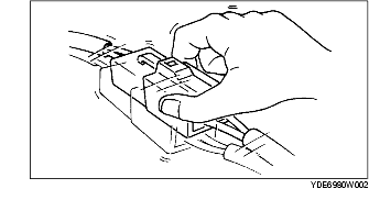
Inspection method for sensor connectors or wires
1. Connect WDS or equivalent to DLC.
2. Turn ignition key to ON (Engine OFF).
-
Note
-
• If engine starts and runs, perform the following steps at idle.
3. Access PIDs for the switch you are inspecting.
4. Shake each connector or wire harness a bit vertically and horizontally while monitoring the PID.
-
• If PID value is unstable, check for poor connection.
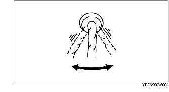
Inspection method for sensors
1. Connect WDS or equivalent to DLC.
2. Turn ignition key to ON (Engine OFF).
-
Note
-
• If engine starts and runs, perform the following steps at idle.
3. Access PIDs for the switch you are inspecting.
4. Vibrate the sensor slightly with your finger.
-
• If PID value is unstable or malfunction occurs, check for poor connection and/or poorly mounted sensor.
Malfunction data monitor method
1. Perform malfunction reappearance test according to malfunction reappearance mode and malfunction data monitor. The malfunction cause is found in the malfunction data.
Malfunction data monitor using SST (ABS/TCS: 49 G066 001, DSC: 49 G066 004)
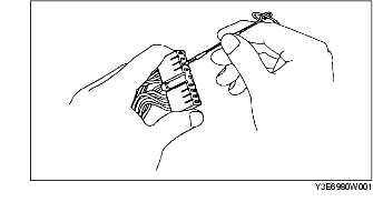
Connector terminal check method
1. Check the connection condition of each female terminal.
2. Insert male terminal; fit female terminal size to female terminal and check to see whether malfunction is in female terminal or not.