|
STEP
|
INSPECTION
|
ACTION
|
|
1
|
INSPECT ABS/TCS HU/CM POWER SUPPLY FUSE
Is ABS/TCS HU/CM ignition power supply fuse okay?
|
Yes
|
Go to next step.
Check for a short to ground on blown fuse's circuit.
|
|
No
|
Repair or replace as necessary.
Install appropriate amperage fuse.
|
|
2
|
INSPECT WIRING HARNESS BETWEEN ABS/TCS HU/CM AND DLC-2 (DATA LINK CONNECTOR-2) FOR CONTINUITY AND SHORTS
Perform DTC inspection.
Is error message displayed regarding communication between ABS/TCS HU/CM and WDS or equivalent?
|
Yes
|
If a communication error message is displayed even after inspecting according to procedure displayed on WDS or equivalent, go to step 8.
|
|
No
|
Go to next step.
|
|
3
|
CHECK FOR DTCS IN ABS/TCS HU/CM
Have DTCs been recorded in memory?
|
Yes
|
Perform inspection using appropriate DTC.
|
|
No
|
Go to next step.
|
|
4
|
INSPECT PID/DATA IN ABS/TCS HU/CM
Inspect the following items using WDS or equivalent PID/DATA monitor function.
• ABS_LAMP (ABS warning light)
• BRAKE_ LAMP (BRAKE system warning light)
• ABS_VOLT (power supply voltage)
Is ABS_LAMP and BRAKE_LAMP ON after more than 4 seconds with ignition switch on?
|
Yes
|
Go to Step 7.
|
|
No
|
Go to next step.
|
|
5
|
CHECK FOR OPEN CIRCUIT IN ABS/TCS HU/CM
Disconnect ABS/TCS HU/CM connector.
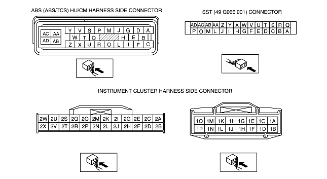
Connect the SST (49 G066 001) (vehicle harness side only).
Use the SST connector to ground the warning light terminal (ABS: terminal W, BRAKE system: terminal X) to body ground.
Do both ABS warning light and BRAKE system warning light go out with ignition switch on?
|
Yes
|
Replace ABS/TCS HU/CM (open circuit in ABS/TCS HU/CM)
|
|
No
|
Go to next step.
|
|
6*
|
VERIFY WHETHER MALFUNCTION IS IN WIRING HARNESS (BETWEEN INSTRUMENT CLUSTER AND ABS/TCS HU/CM FOR CONTINUITY) OR INSTRUMENT CLUSTER
Disconnect instrument cluster connector
Is there continuity between following ABS/TCS HU/CM connector terminals and instrument cluster connector terminals?
• Terminal X and terminal 2F (16 pin)
• Terminal W and terminal 2F (24 pin)
|
Yes
|
Replace instrument cluster (open or short to ground in instrument cluster).
|
|
No
|
Repair wiring harness between ABS/TCS HU/CM (ABS: terminal W, BRAKE warning: terminal X) and instrument cluster
|
|
7
|
INSPECT ABS/TCS HU/CM IGNITION POWER SUPPLY SYSTEM (TERMINAL Z)
Check the voltage for PID/DATA monitor ABS_VOLT item.
Specification: about 10 V
Is voltage within specification?
|
Yes
|
Replace ABS/TCS HU/CM (open or short in ground circuit in ABS/TCS HU/CM)
|
|
No
|
Go to next step.
|
|
8
|
INSPECT BATTERY
Is battery voltage normal?
|
Yes
|
Go to next step.
|
|
No
|
Inspect battery and charging system.
|
|
9
|
INSPECT CHARGING SYSTEM
Is battery voltage normal with electrical load (A/C, headlight, etc.) on and engine idling?
|
Yes
|
Go to Step 7.
|
|
No
|
Inspect charging system (drive belt tension, generator, etc.).
|
|
10
|
VERIFY THAT ABS/TCS HU/CM CONNECTOR IS CONNECTED WITH ABS/TCS HU/CM
Is ABS/TCS HU/CM connector securely connected?
|
Yes
|
Go to Step 12.
|
|
No
|
Connect ABS/TCS HU/CM connector securely, then go to next step.
|
|
11
|
VERIFY THAT MALFUNCTION SYMPTOM OCCURS AFTER ABS/TCS HU/CM IS CONNECTED
Do both ABS warning light and BRAKE system warning light go out after more than 4 seconds with ignition switch on?
|
Yes
|
Temporary poor connection in ABS/TCS HU/CM
Inspect connector and terminal.
|
|
No
|
Go to next step.
|
|
12
|
VERIFY THAT ABS/TCS HU/CM CONNECTOR TERMINAL Z AND AA ARE CONNECTED
Does malfunction symptom happen again when ABS/TCS HU/CM connector terminal Z and AA are shaken while the ignition switch ON?
|
Yes
|
Connect ABS/TCS HU/CM connector terminal Z and AA securely, then go to next step.
|
|
No
|
Go to next step.
|
|
13
|
VERIFY THAT MALFUNCTION SYMPTOM OCCURS AFTER ABS/TCS HU/CM CONNECTOR TERMINALs Z AND AA ARE CONNECTED
Do both ABS warning light and BRAKE system warning light go out after more than 4 seconds with ignition switch on?
|
Yes
|
Temporary poor connection in ABS/TCS HU/CM
Inspect connector and terminal.
|
|
No
|
Go to next step.
|
|
14
|
INSPECT WIRING HARNESS BETWEEN ABS/TCS HU/CM POWER SUPPLY AND ABS/TCS HU/CM FOR CONTINUITY
Disconnect ABS/TCS HU/CM connector.
Connect the SST (49 G066 001) (vehicle harness side only).
Is voltage approximately 12 V at SST connector terminal Z?
|
Yes
|
Go to next step.
|
|
No
|
Repair wiring harness between fuse block and ABS/TCS HU/CM
|
|
15
|
INSPECT WIRING HARNESS BETWEEN ABS/TCS HU/CM GROUND FOR CONTINUITY
Turn ignition switch to LOCK.
Is there continuity between SST connector terminal AA and ground?
|
Yes
|
If a malfunction error message is displayed on WDS or equivalent in Step 1 inspection, go to next step.
If a malfunction error message is not displayed on WDS or equivalent in Step 1 inspection, troubleshooting is completed.
|
|
No
|
Repair wiring harness between ABS/TCS HU/CM and ground.
|
|
16
|
INSPECT WIRING HARNESS BETWEEN ABS/TCS HU/CM AND DLC-2 (DATA LINK CONNECTOR-2) FOR CONTINUITY
Is there continuity between SST connector terminal AA and DLC-2?
|
Yes
|
Go to next step.
|
|
No
|
Repair wiring harness between ABS/TCS HU/CM and DLC-2.
|
|
17
|
INSPECT WIRING HARNESS BETWEEN ABS/TCS HU/CM AND DLC-2 (DATA LINK CONNECTOR-2) FOR SHORT TO BATTERY
Is voltage approximately 12 V at SST connector terminal T?
|
Yes
|
Repair wiring harness between ABS/TCS HU/CM and DLC-2.
|
|
No
|
Go to next step.
|
|
18
|
INSPECT WIRING HARNESS BETWEEN ABS/TCS HU/CM AND DLC-2 (DATA LINK CONNECTOR-2) FOR SHORT TO GROUND
Is there continuity between SST connector Terminal T and DLC-2?
|
Yes
|
Repair wiring harness between ABS/TCS HU/CM and DLC-2.
|
|
No
|
Replace ABS/TCS HU/CM (communication circuit malfunction in ABS/TCS HU/CM)
|
|
|