|
STEP
|
INSPECTION
|
ACTION
|
|
1
|
INSPECT WIRING HARNESS BETWEEN ABS/TCS HU/CM AND DLC-2 (DATA LINK CONNECTOR-2) FOR CONTINUITY AND SHORTS
Perform DTC inspection.
Is error message displayed regarding communication between ABS/TCS HU/CM and WDS or equivalent?
|
Yes
|
If the communication error message is displayed even after inspecting according to procedures displayed in the WDS or equivalent, go to Step 8.
|
|
No
|
Go to next step.
|
|
2
|
CHECK FOR DTCs IN ABS/TCS HU/CM
Have DTCs been recorded in memory?
|
Yes
|
Perform inspection using appropriate DTC.
|
|
No
|
Go to next step.
|
|
3
|
INSPECT PID/DATA IN ABS/TCS HU/CM
Inspect the following items using WDS or equivalent PID/DATA monitor function.
• ABS_LAMP (ABS warning light)
Is ABS_LAMP ON after more than 4 seconds with ignition switch on?
|
Yes
|
Replace ABS/TCS HU/CM (open circuit or short to ground in ABS/TCS HU/CM).
|
|
No
|
Go to next step.
|
|
*4
|
VERIFY THAT ABS/TCS HU/CM CONNECTOR TERMINAL W IS CONNECTED
Does malfunction symptom happen again when ABS/TCS HU/CM connector terminal W is shaken while the ignition switch is ON?
|
Yes
|
Connect ABS/TCS HU/CM connector terminal W securely, then go to next step.
|
|
No
|
Go to next step 6.
|
|
5
|
VERIFY THAT MALFUNCTION SYMPTOM OCCURS AFTER ABS/TCS HU/CM CONNECTOR TERMINAL W IS CONNECTED
Do ABS warning light go out after more than 4 seconds with ignition switch on?
|
Yes
|
Temporary poor connection at terminal.
Inspect ABS/TCS HU/CM connector and terminal.
|
|
No
|
Go to next step.
|
|
*6
|
CHECK FOR OPEN CIRCUITS IN ABS/TCS HU/CM
Disconnect ABS/TCS HU/CM connector.
Connect the SST (49 G066 001) (vehicle harness side only).
Use the SST connector to ground ABS warning light terminal W to body ground.
Does ABS warning light go out with ignition switch on?
|
Yes
|
Replace ABS/TCS HU/CM (open circuit in ABS/TCS HU/CM).
|
|
No
|
Go to next step.
|
|
*7
|
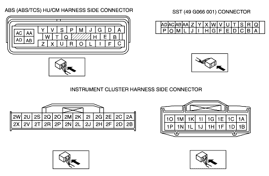
VERIFY SHETHER MALFUNCTION IS IN WIRING HARNESS (BETWEEN INSTRUMENT CLUSTER AND ABS/TCS HU/CM FOR CONTINUITY) OR INSTRUMENT CLUSTER
Is there continuity between following SST connector terminal W and instrument cluster connector (24-pin) terminal 2F?
|
Yes
|
Replace instrument cluster (open or ground to short in instrument cluster).
|
|
No
|
Repair wiring harness between ABS/TCS HU/CM (terminal W) and instrument cluster.
|
|
*8
|
INSPECT WIRING HARNESS BETWEEN ABS/TCS HU/CM AND DLC-2 (DATA LINK CONNECTOR-2) FOR CONTINUITY
Disconnect ABS/TCS HU/CM connector.
Connect the SST (49 G066 001) (vehicle harness side only).
Is there continuity between SST connector terminal T and data link connector?
|
Yes
|
Go to next step.
|
|
No
|
Repair wiring harness between ABS/TCS HU/CM and data link connector.
|
|
*9
|
INSPECT WIRING HARNESS BETWEEN ABS/TCS HU/CM AND DLC-2 (DATA LINK CONNECTOR-2) FOR SHORT TO B+
Is voltage approximately 12V at SST connector terminal T?
|
Yes
|
Repair wiring harness between ABS/TCS HU/CM and data link connector.
|
|
No
|
Go to next step.
|
|
*10
|
INSPECT WIRING HARNESS BETWEEN ABS/TCS HU/CM AND DLC-2 (DATA LINK CONNECTOR-2) FOR SHORT TO GROUND
Is there continuity between SST connector terminal T and ground?
|
Yes
|
Repair wiring harness between ABS/TCS HU/CM and data link connector.
|
|
No
|
Replace ABS/TCS HU/CM (communication circuit malfunction is ABS/TCS HU/CM).
|
|
|