 |
a6e5614w002
MECHANICAL SYSTEM TEST [FN4A-EL]
id0517a1802100
Mechanical System Test Preparation
1. Engage the parking brake and use wheel chocks at the front and rear of the wheels.
2. Inspect the engine coolant. (See ENGINE COOLANT LEVEL INSPECTION [LF, L3].)
3. Inspect the engine oil. (See ENGINE OIL LEVEL INSPECTION [LF, L3].)
4. Inspect the ATF levels. (See AUTOMATIC TRANSAXLE FLUID (ATF) INSPECTION [FN4A-EL].)
5. Inspect the idle speed and ignition timing in P position. (See IDLE SPEED INSPECTION [LF, L3].) (See IGNITION TIMING INSPECTION [LF, L3].)
6. Bring up the engine and transaxle to normal operating temperature.
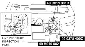
Line Pressure Test
1. Perform mechanical system test preparation. (See Mechanical System Test Preparation.)
2. Connect the SSTs (49 H019 002 and, 49 0378 400C) to the line pressure inspection port, then replace the gauge of the SST (49 0378 400C) with the SST (49 B019 901B).
a6e5614w002
|
3. Start the engine, then warm up the automatic transaxle.
4. Shift the selector lever to D range.
5. Read the line pressure at idle engine speed for the D range.
6. Read the line pressure at idle engine speed for the D (HOLD), S, S (HOLD), L, L (HOLD) ranges and R positions in the same manner as in Steps 4-5. (4AT)
7. Stop the engine, then replace the SST (49 B019 901B) with the gauge of the SST (49 0378 400C).
8. Start the engine.
9. Firmly depress the brake pedal with the left foot.
10. Shift the selector lever to D range position.
11. Gradually depress the accelerator pedal with the right foot.
12. When the engine speed no longer increases, quickly read the line pressure and release the accelerator pedal.
13. Shift the selector lever to N position and let the engine idle for 1 minute or more to cool the ATF.
14. Read the line pressure at the engine stall speed for the D, D (HOLD), S, S (HOLD), L, L(HOLD) ranges and R position in the same manner as in Steps 9-13. (4AT)
Line pressure
|
Position/Range |
Specification (kPa {kgf/cm2, psi}) |
||
|---|---|---|---|
|
LF |
L3 |
||
|
D, S*, L*
*: 4AT
|
idle
|
330—470 {3.4—4.8, 48—68}
|
|
|
Stall
|
1,160—1,320 {11.8—13.5, 168—191}
|
||
|
R
|
idle
|
490—710 {5.0—7.2, 71—102}
|
|
|
Stall
|
1,520—1,820 {15.5—18.5, 221—263}
|
1,640—1,970 {16.8—20.0, 238—285}
|
|
15. Remove the SSTs.
16. Install a new square head plug in the inspection port.
Evaluation of line pressure test
|
Condition |
Possible cause |
|---|---|
|
Low pressure in all position/ranges
|
Worn oil pump
Oil leaking from oil pump, control valve body, and/or transaxle case
Pressure regulator valve sticking
Pressure control solenoid malfunction
Pressure modulator valve sticking
Solenoid reducing valve sticking
|
|
Low pressure in D, S, L ranges
|
Oil leaking from hydraulic circuit of forward clutch
|
|
Low pressure in D (HOLD), S (HOLD) ranges
|
Oil leaking from hydraulic circuit of 2-4 brake band
|
|
Low pressure in L (HOLD) range, R position
|
Oil leaking from hydraulic circuit of low and reverse brake
|
|
Low pressure in R position
|
Oil leaking from hydraulic circuit of reverse clutch
|
|
High pressure in all position/ranges
|
Pressure control solenoid malfunction
Pressure regulator valve sticking
Pressure modulator valve sticking
Pressure reducing valve sticking
|
Stall Test
1. Perform mechanical system test preparation. (See Mechanical System Test Preparation.)
2. Start the engine.
3. Firmly depress the brake pedal with the left foot.
4. Shift the selector lever to D range.
5. Gently depress the accelerator pedal with the right foot.
6. When the engine speed no longer increases, quickly read the speed and release the accelerator pedal. When the engine speed no longer increases, quickly read the speed and release the accelerator pedal.
7. Shift the selector lever to N position and let the engine idle for 1 minute or more to cool the ATF.
8. Perform a stall test of D (HOLD), S, S (HOLD), L, L (HOLD) and R range positions in the same manner as in Steps 3—7. (4AT)
9. Turn the ignition switch off.
Engine stall speed
|
Position/Range |
Specification (rpm) |
|
|---|---|---|
|
LF |
L3 |
|
|
D, S*, L*
*: 4AT
|
2,000—2,600
|
2,100—2,800
|
|
R
|
||
Evaluation of stall test
|
Condition |
Possible cause |
||
|---|---|---|---|
|
Above specification
|
In all position/ranges
|
Insufficient line pressure
|
Worm oil pump
|
|
Oil leaking from oil pump, control valve, and/or transaxle case
|
|||
|
Pressure regulator valve sticking
|
|||
|
Pressure control solenoid malfunction
|
|||
|
Pressure modulator valve sticking
|
|||
|
In D, S, L ranges
|
Forward clutch slippage
|
||
|
In D range
|
One-way clutch malfunction
|
||
|
In D, D (HOLD), S (HOLD) ranges
|
2-4 brake band slippage
One-way clutch malfunction
|
||
|
In D, L (HOLD) ranges
|
Low and reverse brake slippage
One-way clutch malfunction
|
||
|
In R position
|
Low and reverse brake slippage
Reverse clutch slipping
Perform road test to determine whether problem is low and reverse brake or reverse clutch
• Engine braking felt in L (HOLD) range: Reverse clutch
• Engine braking not felt in L (HOLD) range: Low and reverse brake
|
||
|
Below specification
|
Engine out of tune
|
||
|
One-way clutch slipping within torque converter
|
|||
Time Lag Test
1. Perform mechanical system test preparation. (See Mechanical System Test Preparation.)
2. Use a stopwatch to measure the time it takes from shifting until shock is felt when shifting the selector lever from N position to D range (non-HOLD mode). Take three measurements for each test and take the average from the results using the following formula.
3. Perform the test for the following shifts in the same manner Step 2.
Evaluation of time lag test
|
Condition |
Possible Cause |
|
|---|---|---|
|
N → D shift
|
More than specification
|
Insufficient line pressure
Forward clutch slipping
Oil leaking from forward clutch fluid circuit
Shift solenoid A not operating properly
|
|
Less than specification
|
Forward accumulator not operating properly
Shift solenoid A not operating properly
Excessive line pressure
|
|
|
N → D (HOLD) shift*
|
More than specification
|
Insufficient line pressure
Forward clutch slipping
Shift solenoid A not operating properly
|
|
Less than specification
|
Forward accumulator not operating properly
Shift solenoid A not operating properly
Excessive line pressure
|
|
|
N → R shift
|
More than specification
|
Insufficient line pressure
Low and reverse brake slipping
Reverse clutch slipping
Shift solenoid B not operating properly
|
|
Less than specification
|
Servo apply accumulator not operating properly
Shift solenoid B not operating properly
Excessive line pressure
|
|