 |
a6e0612w044
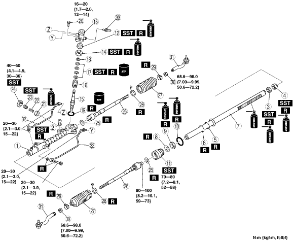
STEERING GEAR AND LINKAGE ASSEMBLY
id061400801200
1. Assemble in the order indicated in the table.
a6e0612w044
|
|
1
|
Gear housing
|
|
2
|
Mounting rubber
|
|
3
|
Oil seal
|
|
4
|
Inner guide
|
|
5
|
O-ring
|
|
6
|
Seal ring
|
|
7
|
Steering rack
|
|
8
|
Backup ring
|
|
9
|
U-gasket
|
|
10
|
O-ring
|
|
11
|
Holder
(See Holder Assembly Note)
|
|
12
|
Oil seal
(See Oil Seal Assembly Note)
|
|
13
|
Valve housing
|
|
14
|
Upper bearing
|
|
15
|
Pinion shaft
|
|
16
|
Control valve
|
|
17
|
Seal ring
(See Seal Ring Assembly Note)
|
|
18
|
Snap ring
|
|
19
|
O-ring
|
|
20
|
Bolt
|
|
21
|
Support yoke
|
|
22
|
Yoke spring
|
|
23
|
Adjusting cover
|
|
24
|
Locknut (adjusting cover)
|
|
25
|
Washer
|
|
26
|
Tie rod
|
|
27
|
Boot
|
|
28
|
Boot band
|
|
29
|
Boot clamp
|
|
30
|
Locknut
|
|
31
|
Tie-rod end
|
|
32
|
Oil pipe
|
|
33
|
Return pipe
|
Mounting Rubber Assembly Note
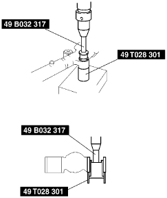
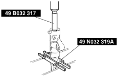
1. Apply soapy water to the rubber part of the mounting rubber.
2. Press the mounting rubber until the mounting rubber end comes out completely from the gear housing using the SSTs and a press.
a6e0612w087
|
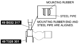
3. Reverse the gear housing, then press the mounting rubber until the mounting rubber end comes out completely from the other side. At this time, mounting rubber end and steel pipe are aligned.
a6e0612w088
|
Oil Seal, Inner Guide Assembly Note
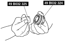
1. Install a new O-ring and a new seal ring to the rack’s piston.
2. After installing the seal ring, seat it properly at the piston circumference.
3. Apply grease to a new oil seal and inner guide.
4. Install the oil seal to the SST.
a6e0612w048
|
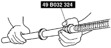
5. Using the SST, place the oil seal and inner guide at the edge of the steering rack’s pinion, and remove the SST.
a6e0612w049
|
6. After installing the steering rack to the gear housing, press the oil seal and inner guide using the SSTs until the force required suddenly increases.
a6e0612w039
|
Holder Assembly Note
1. Apply grease to the U-gasket and O-ring.
2. Assemble the U-gasket, backup ring and O-ring into the holder.
3. Assemble the SST to the steering rack.
a6e0612w090
|
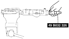
4. Stake the holder to the cylinder using a punch.
a6e6316w012
|
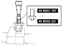
Oil Seal Assembly Note
1. Apply grease to a new oil seal.
2. Press in the new oil seal using the SSTs.
a6e0612w036
|
Upper Bearing Assembly Note
1. Apply grease to a new upper bearing.
2. Press in the upper bearing using the SST.
a6e0612w051
|
Seal Ring Assembly Note
1. Install a new seal ring to the valve part of the pinion shaft using the SST.
2. After installing it, seat it properly using the SST.
a6e0612w052
|
3. Install the snap ring.
Adjusting Cover Assembly Note
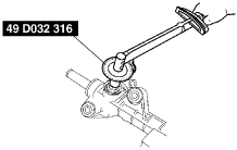
1. Set the rack to the center position.
2. Tighten the adjusting cover to 4.9 N·m {50 kgf·cm, 36 in·lbf} three times, then return it 25° using the SST.
a6e0612w062
|
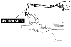
3. Apply sealant to the threads of the locknut.
4. Attach the locknut.
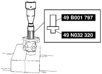
5. Measure the pinion torque using the SST and a pull scale.
a6e0612w042
|
6. If not as specified, repeat steps 2 through 5.
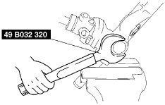
7. Install the locknut using the SST (49 B032 320).
a6e0612w056
|
Hermetic sealing inspection
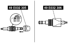
1. Connect the SSTs to the power cylinder section of the gear housing.
2. Apply 53.3 kPa {400 mmHg, 15.7 inHg}vacuum with a vacuum pump and verify that it is held for at least 30 seconds.
a6e0612w054
|
3. If the vacuum is not held, replace the oil seal.
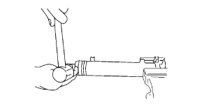
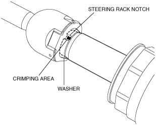
Washer and Tie Rod Assembly Note
1. Assemble the washer and tie rod to the steering rack and tighten the tie rod to the specified torque.
2. Crimp the areas where the washer and the steering rack notch overlap (2 locations) using a punch.
am6uuw00001870
|