ON-BOARD DIAGNOSTIC FUNCTION
id070200100300
Outline
• Based on the sunlight intensity and temperature signals from the various sensors, the climate control unit performs very complex control to the output actuation devices. Therefore, the operating condition of the output devices may vary due to input conditions, even though the controls on the climate control unit are not changed. As a result, when a malfunction occurs in the control system, it may be difficult to reproduce the symptom and to isolate the malfunctioning part of the system. To avoid such difficulty, the climate control unit is programmed with a on-board diagnostic function which input system is malfunctioning. It can also check the output system separately from the input system.
• The on-board diagnostic function has three modes: present failure indication, past failure indication, and output device operation check.
• The climate control unit terminal 1F is connected to the body ground by the body grounding of the A/C check connector, whereby voltage fluctuation occurs. The climate control unit detects this voltage fluctuation and activates the on-board diagnostic function.
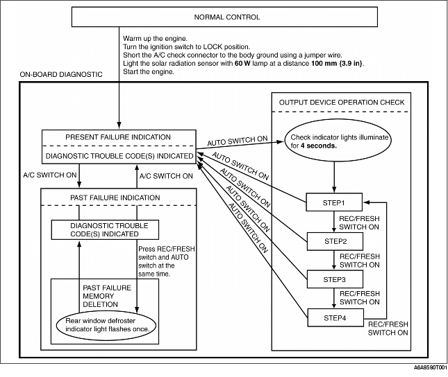
Present Failure Indication Mode
• In present failure indication mode, present failures in the control system circuits (open, short circuits) are detected, and the flashing of the DEFROSTER switch indicator light on the climate control unit indicates the DTCs shown in the table below.
Past Failure Indication Mode
• In past failure indication mode, past failures (intermittent problems) in the input sensor circuits (open, short circuits) are stored, and the flashing of the DEFROSTER switch indicator light on the climate control unit indicates the DTCs shown in the table below. Erase DTCs from the memory after failures have been corrected so they are not maintained as past failures.
Diagnostic trouble codes
|
DTC No.
|
Indicator pattern
|
Diagnosed circuit
|
Detected condition
|
Memo rized
|
|
02
|

|
Solar radiation sensor (present)
|
Open circuit in solar radiation sensor circuit
Short circuit in solar radiation sensor circuit (terminal B side only)
|
No
|
|
06
|

|
Cabin temperature sensor (present)
|
Open/short circuit is in cabin temperature sensor circuit
|
No
|
|
07
|

|
Cabin temperature sensor (past)
|
Cabin temperature sensor circuit is entered fail-safe mode at least once
|
Yes
|
|
10
|

|
Evaporator temperature sensor (present)
|
Open/short circuit is in evaporator temperature sensor circuit
|
No
|
|
11
|

|
Evaporator temperature sensor (past)
|
Evaporator temperature sensor circuit is entered fail-safe mode at least once
|
Yes
|
|
12
|

|
Ambient temperature sensor (present)
|
Open/short circuit is in Ambient temperature sensor circuit
|
No
|
|
13
|

|
Ambient temperature sensor (past)
|
Ambient temperature sensor circuit is entered fail-safe mode at least once
|
Yes
|
|
14
|

|
Water temperature sensor (present)
|
Open/short circuit is in Water temperature sensor circuit
|
No
|
|
15
|

|
Water temperature sensor (past)
|
Water temperature sensor circuit is entered fail-safe mode at least once
|
Yes
|
|
18
|

|
Air mix actuator (potentiometer) (present)
|
Open/short circuit is in air mix actuator (potentiometer) circuit
|
No
|
|
19
|

|
Air mix actuator (potentiometer) (past)
|
Air mix actuator (potentiometer) circuit is entered fail-safe mode at least once
|
Yes
|
|
21
|

|
Airflow mode actuator (potentiometer) (present)
|
Open/short circuit is in airflow mode actuator (potentiometer) circuit
|
No
|
|
22
|

|
Airflow mode actuator (potentiometer) ( (past)
|
Airflow mode actuator (potentiometer) circuit is entered fail-safe mode at least once
|
Yes
|
|
58
|
|
Air mix actuator (motor lock) (past)
|
Air mix actuator circuit is entered fail-safe mode at least once
|
Yes
|
|
59
|
|
Airflow mode actuator (motor lock) (past)
|
Airflow mode actuator circuit is entered fail-safe mode at least once
|
Yes
|
Output Device Operation Check Mode
• In the output device operation check mode, the climate control unit forces all the output system actuation devices to operate regardless of the input system. The displays change and the switch indicator lights illuminate automatically according to the actuator operated.
• Inspect visually, listen for operation sound, and place hands over air discharge outlets to check for correct operating conditions and to locate the malfunctioning system.
Output device operation check table
|
Step
|
Operating device
|
Operating conditions
|
Moni tor*
|
Other device conditions
|
|
1
|
Blower motor speed
|
|
1
|
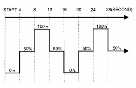
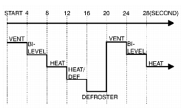
• Air mix actuator operation
-
- 50%
• Airflow mode actuator operation
-
- VENT
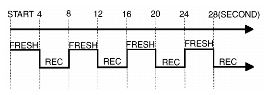
• Air intake actuator operation
-
- FRESH
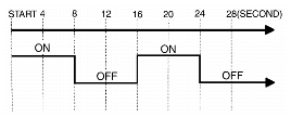
• A/C compressor operation
-
- ON
|
|
2
|
Air mix actuator operation
|
|
21.0
|
• Blower motor speed
-
- 3rd
• Airflow mode actuator operation
-
- VENT
• Air intake actuator operation
-
- FRESH
• A/C compressor operation
-
- ON
|
|
20.5
|
|
20.0
|
|
3
|
Airflow mode actuator operation
|
|
3
|
• Blower motor speed
-
- 3rd
• Air mix actuator operation
-
- 50%
• Air intake actuator operation
-
- FRESH
• A/C compressor operation
-
- ON
|
|
4
|
Air intake actuator operation
|
|
4
|
• Blower motor speed
-
- 3rd
• Air mix actuator operation
-
- 0%
• Airflow mode actuator operation
-
- VENT
|
|
A/C compressor operation
|
|
-
* :
Shown on the information display according to step.