AIRFLOW VOLUME CONTROL OPERATION


id074000102600

Airflow Volume Automatic Control

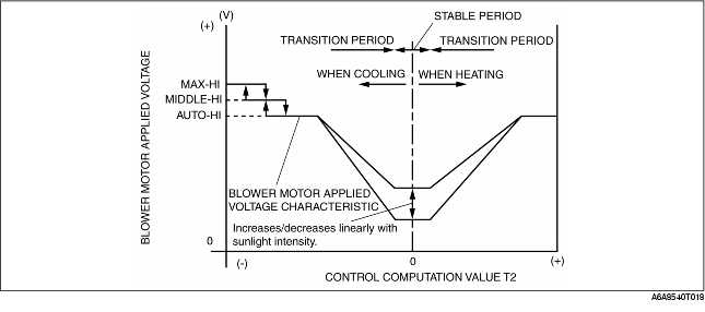
• Based on the set temperature, the ambient temperature, and sunlight intensity, the climate control unit calculates the blower motor voltage characteristic (AUTO voltage). It compares the differences among this voltage characteristic, and the target temperature (control computation value T2) and then determines the voltage to be applied to the blower motor.

Correction

Coolant temperature correction (warm-up correction)
• To prevent a large volume of cold air from blowing through the ventilation outlets when the engine is started in winter, coolant temperature control links the blower motor voltage to the rise in engine coolant temperature. However, coolant temperature correction does not operate when the defroster correction is running, when the cabin temperature is above 20°C {68°F}, or when airflow is in VENT mode.

Mild start correction
• To prevent a large volume of warm air from blowing through the ventilation outlets when the blower motor is started in summer, the voltage applied to the blower motor is restricted for 3 seconds after it starts. However, mild start correction does not operate when the passenger compartment temperature is below 20°C {68°F}, or when airflow is in any mode other than VENT.

MAX HOT and MAX COLD correction
• When the temperature is set to MAX HOT (32.0: R.H.D., intensely hot area or 29.0: L.H.D. (intensely hot area)), the applied voltage of the blower motor is set at AUTO-HI, when at MAX COLD (18.0: R.H.D., intensely hot area or 15.0: L.H.D. (intensely hot area)), the applied voltage of the blower motor is set at MAX-HI. However, when in water temperature correction, MAX HOT correction does not take place.

Correction

Set temperature

Blower motor applied voltage

MAX HOT
32.0 (R.H.D., intensely hot area)
29.0 (L.H.D. (except intensely hot area))
12.1 (V): AUTO-HI
MAX COLD
18.0 (R.H.D., intensely hot area)
15.0 (L.H.D. (except intensely hot area))
B+: MAX-HI

Windshield mist prevention correction
• To prevent the air blown from the defroster when the heater is started in winter from clouding the windows, the blower motor and the A/C signal output are switched off for 6 seconds after the ignition is turned to the ON position. This control only operates if the airflow is in HEAT, HEAT/DEF, or DEFROSTER mode.
Start compensation correction
• When the blower motor is started at 3.2 V, it is run at a voltage of 4.4 V for 2 seconds to help it stabilize at the target voltage.
Defroster correction
• To improve defrosting and heating, 2.0 V is added to the AUTO voltage calculated airflow volume automatic control when the defroster switch is turned on.
Fail-safe function
• If the blower motor is started with more than 4.4 V, a surge will occur and the motor may burn. To prevent this, the voltage applied to the blower motor is regulated to 4.4 V for 1 second when it is started.

Airflow Volume Manual Control

• The blower motor (airflow) has seven speeds and is operated by the fan switch.

Fan speed

Switch operation

Control device

Blower motor voltage

1st
Airflow volume automatic control, manual 2nd (-), manual 1st (-) or OFF (+ or -)
→manual 1st
Power MOS FET
4.4 (V)
2nd
Airflow volume automatic control, manual 1st (+), or manual 3rd (-)
→manual 2nd
Power MOS FET
6.1 (V)
3rd
Airflow volume automatic control, manual 2nd (+), or manual 4th (-)
→manual 3rd
Power MOS FET
7.8 (V)
4th
Airflow volume automatic control, manual 3rd (+), or manual 5th (-)
→manual 4th
Power MOS FET
9.5 (V)
5th
Airflow volume automatic control, manual 4th (+), or manual 6th (-)
→manual 5th
Power MOS FET
10.8 (V)
6th
Airflow volume automatic control, manual 5th (+), or manual 7th (-)
→manual 6th
Power MOS FET
12.1 (V)
7th
Airflow volume automatic control, manual 6th (+), or manual 7th (+)
→manual 7th
Power MOS FET
B+