PROCEDURES FOR DETERMINING THE LOCATION OF A MALFUNCTION
id0902e6830500
System Wiring Diagram
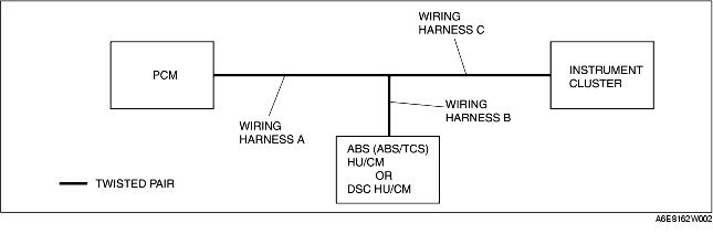
PCM
1. Check the display of DTC U0121 and/or U0155, using the SST (WDS or equivalent). (See DTC TABLE [CAN SYSTEM].)
2. Referring to the following table, determine the malfunctioning part of the CAN system.
X: Normal
-: Communication error
|
Module
|
Communication status
|
Malfunction location
|
|
• ABS (ABS/TCS) HU/CM
• DSC HU/CM
|
Instrument cluster
|
|
PCM
|
-
|
-
|
• Wiring harness A
• PCM
|
|
-
|
X
|
• Wiring harness B
• ABS (ABS/TCS) HU/CM
• DSC HU/CM
|
|
X
|
-
|
• Wiring harness C
• Instrument cluster
|
ABS/TCS HU/CM or DSC HU/CM
1. Access and monitor the "PCM MSG" and "IC MSG" of PID using the SST (WDS or equivalent).
2. Referring to the PID/DATA MONITOR, confirm the display status of the PID. (See PID/DATA MONITOR TABLE [CAN SYSTEM].)
3. Referring to the following table, determine the malfunctioning part of the CAN system.
X: Normal
-: Communication error
|
Module
|
Communication status
|
Malfunction location
|
|
PCM
|
Instrument cluster
|
|
• ABS (ABS/TCS) HU/CM
• DSC HU/CM
|
-
|
-
|
• Wiring harness B
• ABS (ABS/TCS) HU/CM
• DSC HU/CM
|
|
-
|
X
|
• Wiring harness A
• PCM
|
|
X
|
-
|
• Wiring harness C
• Instrument cluster
|
Instrument Cluster
1. Access and monitor the "PCM MSG" and "ABS MSG" of PID using the SST (WDS or equivalent).
2. Referring to the PID/DATA MONITOR, confirm the display status of the PID. (See PID/DATA MONITOR TABLE [CAN SYSTEM].)
3. Referring to the following table, determine the malfunctioning part of the CAN system.
X: Normal
-: Communication error
|
Module
|
Communication status
|
Malfunction location
|
|
PCM
|
• ABS (ABS/TCS) HU/CM
• DSC HU/CM
|
|
Instrument cluster
|
-
|
-
|
• Wiring harness C
• Instrument cluster
|
|
-
|
X
|
• Wiring harness A
• PCM
|
|
X
|
-
|
• Wiring harness B
• ABS (ABS/TCS) HU/CM
• DSC HU/CM
|