1. Inspect the speedometer by setting it in the input/output check mode DTC 12.
1. Adjust the tire air pressure to the specification.
2. Using a speedometer tester, verify that the speedometer indication is within the allowable ranges shown below.
|
Speedometer tester indication (km/h)
|
Allowable range (km/h)
|
|---|---|
|
20
|
18-22
|
|
40
|
38-42
|
|
60
|
58-62
|
|
80
|
78-82
|
|
100
|
98-102
|
|
120
|
117-123
|
|
140
|
137-143
|
|
Speedometer tester indication (mph)
|
Allowable range (mph)
|
|---|---|
|
10
|
9-11
|
|
20
|
19-21
|
|
30
|
29-31
|
|
40
|
39-41
|
|
50
|
49-51
|
|
60
|
59-61
|
|
70
|
69-71
|
|
80
|
78-82
|
3. Verify that fluctuation of the speedometer needle is within the allowable range.
1. Inspect the tachometer by setting it in the input/output check mode DTC 13.
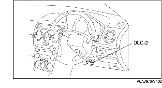
1. Connect the SSTs (WDS or equivalent) to the vehicle DLC-2 16-pin connector.
2. Access and monitor PIDs by SSTs (WDS or equivalent).
1. Inspect the fuel gauge by setting it in the input/output check mode DTC 23.
1. Inspect the water temperature gauge by setting it in the input/output check mode DTC 25.