STEERING SHAFT INSPECTION


id061300801600

1.  Disconnect the negative battery cable. (See NEGATIVE BATTERY CABLE DISCONNECTION/CONNECTION [SKYACTIV-G 2.0, SKYACTIV-G 2.5].) (See NEGATIVE BATTERY CABLE DISCONNECTION/CONNECTION [SKYACTIV-G 2.0, SKYACTIV-G 2.5 (WITHOUT i-stop)].) (See NEGATIVE BATTERY CABLE DISCONNECTION/CONNECTION [SKYACTIV-D 2.2].)

2.  Remove the following parts:

(1)  Upper panel (See UPPER PANEL REMOVAL/INSTALLATION.)
(2)  Rear console (See REAR CONSOLE REMOVAL/INSTALLATION.)
(3)  Console side panel (See CONSOLE SIDE PANEL REMOVAL/INSTALLATION.)
(4)  Selector lever knob (ATX) (See AUTOMATIC TRANSAXLE SHIFT MECHANISM REMOVAL/INSTALLATION.)
(5)  Shift lever knob (MTX) (See MANUAL TRANSAXLE SHIFT MECHANISM REMOVAL/INSTALLATION [C66M-R].) (See MANUAL TRANSAXLE SHIFT MECHANISM REMOVAL/INSTALLATION [D66M-R, D66MX-R].)
(6)  Shift panel (See SHIFT PANEL REMOVAL/INSTALLATION.)
(7)  Front console box (See FRONT CONSOLE BOX REMOVAL/INSTALLATION.)
(8)  CD player (With CD player) (See CD PLAYER REMOVAL.) (See DVD/CD PLAYER INSTALLATION.)
(9)  DVD/CD player (With DVD/CD player) (See DVD/CD PLAYER REMOVAL.) (See DVD/CD PLAYER INSTALLATION.)
(10)  Side wall (See SIDE WALL REMOVAL/INSTALLATION.)
(11)  Front console (See FRONT CONSOLE REMOVAL/INSTALLATION.)
(12)  Driver-side front scuff plate (See FRONT SCUFF PLATE REMOVAL/INSTALLATION.)
(13)  Driver-side front side trim (See FRONT SIDE TRIM REMOVAL/INSTALLATION.)
(14)  Bonnet release lever (See BONNET LATCH AND RELEASE LEVER REMOVAL/INSTALLATION.)
(15)  Fuel-filler lid opener lever (See FUEL-FILLER LID OPENER AND LEVER REMOVAL/INSTALLATION.)
(16)  Driver-side lower panel (See LOWER PANEL REMOVAL/INSTALLATION.)
(17)  Column cover (See COLUMN COVER REMOVAL/INSTALLATION.)

3.  Inspect the steering column for excessive play and damage.

4.  Perform the following procedure for vehicles with the lane-keep assist system.

(1)  Verify that the clearance between the projection on the steering column shown in the figure and the bracket is less than 2.0 mm {0.079 in}.
am3zzw00018065
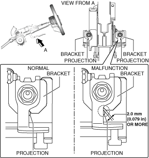
•  If the clearance between the projection and bracket is 2.0 mm {0.079 in} or more, replace the steering column component. (See STEERING WHEEL AND COLUMN REMOVAL/INSTALLATION.)
Note
•  If the clearance between the projection and bracket is 2.0 mm {0.079 in} or more, the impact absorbing mechanism of the steering column will operate, therefore it is necessary to replace the steering column component.