FLOOR COVERING REMOVAL/INSTALLATION
id091700803000
1. Disconnect the negative battery cable. (See NEGATIVE BATTERY CABLE DISCONNECTION/CONNECTION [SKYACTIV-D 2.2].) (See NEGATIVE BATTERY CABLE DISCONNECTION/CONNECTION [SKYACTIV-G 2.0, SKYACTIV-G 2.5].) (See NEGATIVE BATTERY CABLE DISCONNECTION/CONNECTION [SKYACTIV-G 2.0, SKYACTIV-G 2.5 (WITHOUT i-stop)].)
2. Remove the following parts:
- (1) Joint cover (See STEERING WHEEL AND COLUMN REMOVAL/INSTALLATION.)
- (2) Accelerator pedal (See ACCELERATOR PEDAL REMOVAL/INSTALLATION [SKYACTIV-D 2.2].) (See ACCELERATOR PEDAL REMOVAL/INSTALLATION [SKYACTIV-G 2.0, SKYACTIV-G 2.5].)
- (3) Front scuff plate (See FRONT SCUFF PLATE REMOVAL/INSTALLATION.)
- (4) Front side trim (See FRONT SIDE TRIM REMOVAL/INSTALLATION.)
- (5) Rear scuff plate (See REAR SCUFF PLATE REMOVAL/INSTALLATION.)
- (6) B-pillar lower trim (See B-PILLAR LOWER TRIM REMOVAL/INSTALLATION.)
- (7) Lower anchor of the front seat belt (See FRONT SEAT BELT REMOVAL/INSTALLATION.)
- (8) Upper panel (See UPPER PANEL REMOVAL/INSTALLATION.)
- (9) Rear console (See REAR CONSOLE REMOVAL/INSTALLATION.)
- (10) Console side panel (See CONSOLE SIDE PANEL REMOVAL/INSTALLATION.)
- (11) Selector lever knob (ATX) (See AUTOMATIC TRANSAXLE SHIFT MECHANISM REMOVAL/INSTALLATION.)
- (12) Shift lever knob (MTX) (See MANUAL TRANSAXLE SHIFT MECHANISM REMOVAL/INSTALLATION [C66M-R].) (See MANUAL TRANSAXLE SHIFT MECHANISM REMOVAL/INSTALLATION [D66M-R, D66MX-R].)
- (13) Shift panel (See SHIFT PANEL REMOVAL/INSTALLATION.)
- (14) Front console box (See FRONT CONSOLE BOX REMOVAL/INSTALLATION.)
- (15) CD player (with CD player) (See CD PLAYER REMOVAL.) (See CD PLAYER INSTALLATION.)
- (16) DVD/CD player (with DVD/CD player) (See DVD/CD PLAYER REMOVAL.) (See DVD/CD PLAYER INSTALLATION.)
- (17) Side wall (See SIDE WALL REMOVAL/INSTALLATION.)
- (18) Front console (See FRONT CONSOLE REMOVAL/INSTALLATION.)
- (19) Shift lever component (MTX) (See MANUAL TRANSAXLE SHIFT MECHANISM REMOVAL/INSTALLATION [C66M-R].) (See MANUAL TRANSAXLE SHIFT MECHANISM REMOVAL/INSTALLATION [D66M-R, D66MX-R].)
- (20) Selector lever component (ATX) (See AUTOMATIC TRANSAXLE SHIFT MECHANISM REMOVAL/INSTALLATION.)
- (21) Rear vent duct (See REAR VENT DUCT REMOVAL/INSTALLATION.)
- (22) Electric parking brake control module (See ELECTRIC PARKING BRAKE CONTROL MODULE REMOVAL/INSTALLATION.)
- (23) SAS control module (See SAS CONTROL MODULE REMOVAL/INSTALLATION.))
- (24) Front seat (See FRONT SEAT REMOVAL/INSTALLATION.)
- (25) Rear seat cushion (See REAR SEAT CUSHION REMOVAL/INSTALLATION.)
- (26) Audio amplifier (With Bose®) (See AUDIO AMPLIFIER REMOVAL/INSTALLATION.)
3. Disconnect the dashboard harness connectors.
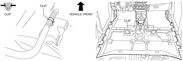
4. Remove the clips shown in the figure.
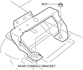
5. Remove nuts.
6. Remove the rear console bracket.
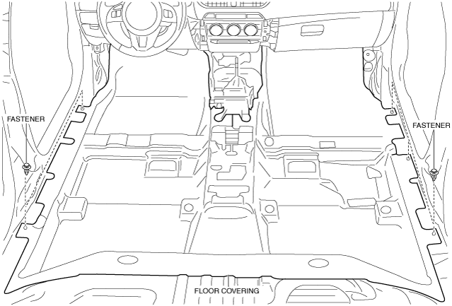
7. Remove the fasteners.
8. Take the floor covering out from the door opening.
9. Install in the reverse order of removal. (See Floor Covering Installation Note.)
Floor Covering Installation Note
-
Caution
-
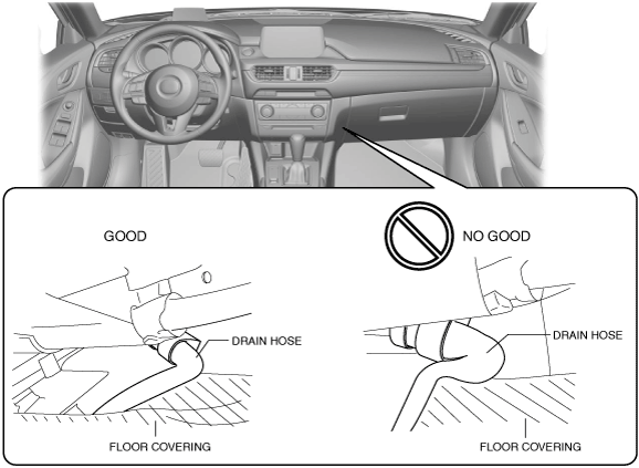
• When installing the floor covering, the floor covering may press the A/C unit drain hose and deform it. When installing the floor covering, align the floor covering to the body to prevent deforming the A/C unit drain hose.
1. Place the floor covering with it aligned to the body.
2. Before installing the side wall, verify that the A/C unit drain hose is not deformed.
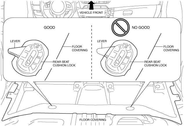
• If the rear seat cushion lock lever is covered by the floor mat, the rear seat cushion lock cannot be released. When installing the floor mat, do not cover the rear seat cushion lock lever with the mat.