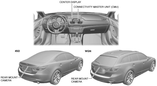
PARKING ASSIST SYSTEM [WITH CENTER DISPLAY]
id0920zz014000
-
Caution
-
• The park assist system is a supplementary system which displays the conditions at the rear of the vehicle when reversing. Always directly confirm the safety of the surrounding area visually when reversing.
Outline
• When the vehicle is reversing, the rear mount camera installed to the trunk lid garnish (4SD)/liftgate garnish (WGN) displays the images at the rear of the vehicle in the center display for verification of the presence of pedestrians and obstructions at the rear of the vehicle.
Function
Rear view monitor display function
-
• When the connectivity master unit (CMU) receives a selector lever R position signal, it displays the images at the rear of the vehicle taken by the rear mount camera in the center display.
Guide line display (With ixed assist lines display type)
-
• The rear mount camera displays the distance reference line on the image at the left front of the vehicle, and the distance reference line and vehicle width extension line on the image at the rear of the vehicle.
Predicted vehicle track display (With predicted vehicle path assist lines display type)
-
• The rear mount camera displays the distance reference line, vehicle width extension line, and predicted vehicle track calculated from the steering angle signal on the image at the rear of the vehicle in the center display.
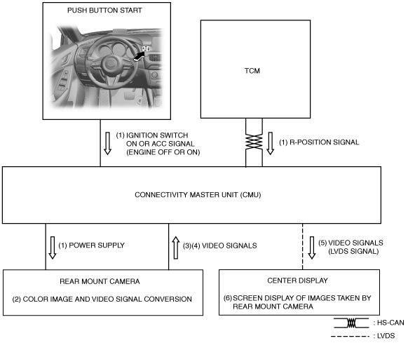
Structural View
Block diagram
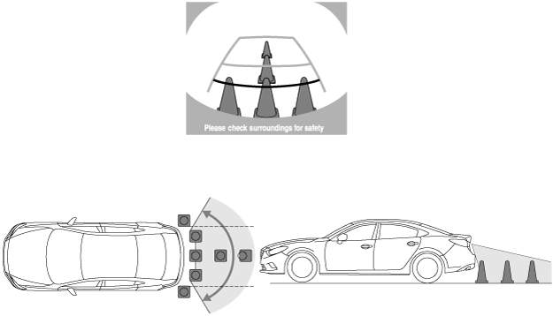
Image range
-
Note
-
• The image range may differ depending on the road surface conditions and the vehicle conditions. In addition, images near both sides of the rear bumper and below the rear bumper cannot be obtained.
Rear view monitor screen
Guide line display (With ixed assist lines display type)
|
Display item
|
Display line color
|
Content
|
|
Distance reference lines (fixed)
|
Red
|
• Shows distance reference line 0.5 m {20 in}from the rear of the rear bumper.
• Not in conjunction with steering operation.
|
|
Yellow
|
• Shows distance reference line 1.0 m {39 in} from the rear of the rear bumper.
• Not in conjunction with steering operation.
|
|
Yellow
|
• Shows distance reference line 2.7 m {106 in} from the rear of the rear bumper.
• Not in conjunction with steering operation.
|
|
Vehicle width extension line
|
Yellow
|
• Vehicle width extension line.
|
|
Bumper area
|
Black
|
• Displays the rear bumper area.
|
Predicted vehicle track display (With predicted vehicle path assist lines display type)
|
Display item
|
Display line color
|
Content
|
|
Distance reference line (in conjunction with steering)
|
Red
|
• Shows distance reference line 0.5 m {20 in} from the rear of the rear bumper.
• Display changes in conjunction with the steering operation.
|
|
Yellow
|
• Shows distance reference line 1.0 m {39 in} from the rear of the rear bumper.
• Display changes in conjunction with the steering operation.
|
|
Yellow
|
• Shows distance reference line 2.7 m {106 in} from the rear of the rear bumper.
• Display changes in conjunction with the steering operation.
|
|
Distance reference lines (fixed)
|
Blue
|
• Shows distance reference line 0.5 m {20 in} from the rear of the rear bumper.
• Not in conjunction with steering operation.
|
|
Vehicle width extension line
|
Blue
|
• Vehicle width extension line.
|
|
Predicted vehicle path line
|
Yellow
|
• Calculated vehicle path based on steering angle signal.
• Predicted vehicle path which expresses the vehicle outermost circumference in conjunction with the steering operation.
|
Operation
-
Caution
-
• Images displayed by the rear mount monitor camera differ depending on the actual conditions resulting from road surface conditions, the number of passengers, and cargo load. Even though it may appear that the vehicle will not come into contact with an object as seen in the image, it may actually come into contact with it. When reversing the vehicle, always verify the surroundings visually.
Guide line display (With ixed assist lines display type)
-
1. When the ignition is switched to ACC or ON (engine off or on) and an R position signal from the selector lever is received (1), the CMU supplies (1) power to the rear mount camera.
2. The rear mount camera shoots the conditions at the rear of the vehicle in color which is converted (2) to a video signal.
3. The rear mount camera combines the distance reference lines (fixed lines) and the vehicle width extension lines with the camera images and converts (3) them to a video signal.
4. The rear mount camera sends (4) the converted video signal to the connectivity master unit (CMU).
5. When a video signal is received from the rear mount camera, the CMU sends the received (5) video signal (LVDS signal) to the center display.
6. The center display displays (6) the images at the rear of the vehicle taken by the rear mount camera based on the received video signal (LVDS signal).
-
Note
-
• It may be difficult to see the display under the following conditions; however, it does not indicate a malfunction:
-
― When the temperature around the lens is high/low.
― When the camera is wet such as on a rainy day or during period of high humidity.
― When foreign material such as mud is stuck around the camera.
― When the camera lens reflects sunlight or headlight beams.
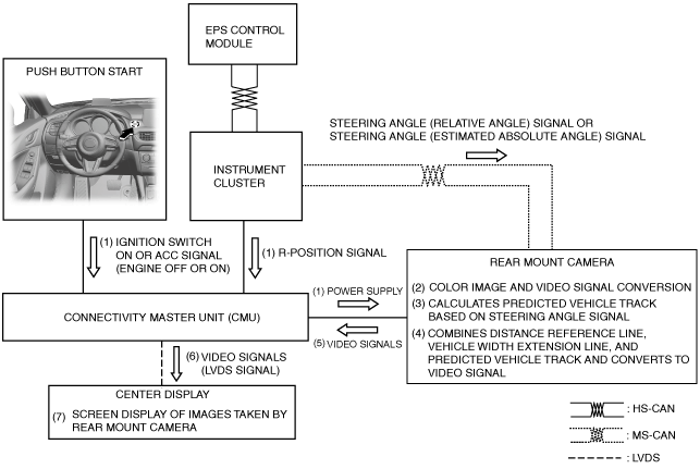
Predicted vehicle track display (With predicted vehicle path assist lines display type)
-
1. When the ignition is switched to ACC or ON (engine off or on) and an R position signal from the selector lever is received (1), the CMU supplies (1) power to the rear mount camera.
2. The rear mount camera shoots the conditions at the rear of the vehicle in color which is converted (2) to a video signal.
3. The rear mount camera calculates (3) the predicted vehicle track based on the steering angle (relative angle) signal and steering angle (estimated absolute angle) signal received from the electric power steering (EPS) control module.
4. The rear mount camera combines (4) the distance reference line, vehicle width extension line, and calculated predicted vehicle track with the camera images and converts them to a video signal.
5. The rear mount camera sends (5) the converted video signal to the connectivity master unit (CMU).
6. When a video signal is received from the rear mount camera, the CMU sends the received (6) video signal (LVDS signal) to the center display.
7. The center display displays (7) the images at the rear of the vehicle taken by the rear mount camera based on the received video signal (LVDS signal).
-
Note
-
• It may be difficult to see the display under the following conditions; however, it does not indicate a malfunction:
-
― When the temperature around the lens is high/low.
― When the camera is wet such as on a rainy day or during period of high humidity.
― When foreign material such as mud is stuck around the camera.
― When the camera lens reflects sunlight or headlight beams.