TIMING CHAIN DISASSEMBLY
id011000505500
-
Caution
-
• If the camshaft is rotated with the timing chain removed and the piston at the top dead center position, the valve may contact the piston and the engine could be damaged. When rotating the camshaft with the timing chain removed, rotate it after lowering the piston from the top dead center position.
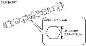
• When rotating the camshaft using a wrench on the cast hexagon, the wrench may contact the rocker arm and damage the rocker arm. To prevent damage to the rocker arm when holding the camshaft on the cast hexagon, use a wrench on the rear side of the engine as shown in the figure to secure a clearance between the cam.
-
Note
-
• Width at the cast hexagon of the camshaft is 22—24 mm {0.87—0.94 in}.
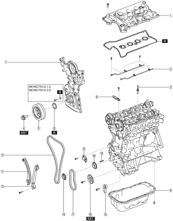
1. Disassemble in the order indicated in the table.
SKYACTIV-G 1.3, SKYACTIV-G 1.5 (Except MX-5 (ND)), SKYACTIV-G 2.0 (Except MX-5 (ND))
|
1
|
Cylinder head cover
|
|
2
|
Oil shower pipe
|
|
3
|
Spark plug
|
|
4
|
Crankshaft pulley lock bolt
|
|
5
|
Crankshaft pulley
|
|
6
|
Oil pan
|
|
7
|
Engine front cover
|
|
8
|
Front oil seal
|
|
9
|
Chain guide (No.1)
|
|
10
|
Chain tensioner
|
|
11
|
Tensioner arm
|
|
12
|
Timing chain
|
|
13
|
Chain guide (No.2)
|
|
14
|
Crankshaft sprocket
|
|
15
|
Oil pump chain tensioner
|
|
16
|
Oil pump driven sprocket
|
|
17
|
Oil pump chain
|
|
18
|
Oil pump drive sprocket
|
|
19
|
Key
|
SKYACTIV-G 1.5 (MX-5 (ND)), SKYACTIV-G 2.0 (MX-5 (ND))
|
1
|
Cylinder head cover
|
|
2
|
Oil shower pipe
|
|
3
|
Spark plug
|
|
4
|
Crankshaft pulley lock bolt
|
|
5
|
Crankshaft pulley
|
|
6
|
Engine hanger
|
|
7
|
Oil pan
|
|
8
|
Engine front cover
|
|
9
|
Front oil seal
|
|
10
|
Chain guide (No.1)
|
|
11
|
Chain tensioner
|
|
12
|
Tensioner arm
|
|
13
|
Timing chain
|
|
14
|
Chain guide (No.2)
|
|
15
|
Crankshaft sprocket
|
|
16
|
Oil pump chain tensioner
|
|
17
|
Oil pump driven sprocket
|
|
18
|
Oil pump chain
|
|
19
|
Oil pump drive sprocket
|
|
20
|
Key
|
SKYACTIV-G 2.5
|
1
|
Cylinder head cover
|
|
2
|
Oil shower pipe
|
|
3
|
Spark plug
|
|
4
|
Crankshaft pulley lock bolt
|
|
5
|
Crankshaft pulley
|
|
6
|
Oil pan
|
|
7
|
Engine front cover
|
|
8
|
Front oil seal
|
|
9
|
Chain guide (No.1)
|
|
10
|
Chain tensioner
|
|
11
|
Tensioner arm
|
|
12
|
Timing chain
|
|
13
|
Chain guide (No.2)
|
|
14
|
Crankshaft sprocket
|
|
15
|
Oil pump chain tensioner
|
|
16
|
Balancer shaft sprocket
|
|
17
|
Oil pump chain
|
|
18
|
Oil pump driven sprocket
|
|
19
|
Oil pump chain guide
|
|
20
|
Oil pump drive sprocket
|
|
21
|
Key
|
Crankshaft Pulley Lock Bolt Disassembly Note
1. Hold the crankshaft using the SST.
2. Remove the crankshaft pulley lock bolt.
Oil Pan Disassembly Note
1. Remove the oil pan using a separator tool.
Engine Front Cover Disassembly Note (with electric variable valve timing)
1. Remove the engine front cover installation bolts.
2. Using a screwdriver wrapped in a cloth, peel the sealant away a little at a time, and remove the engine front cover.
-
Caution
-
• Do not apply excessive force to the screwdriver. Otherwise, the engine front cover could be damaged.
• Be careful not to scratch or damage the seal surface. Otherwise, it could cause oil leakage.
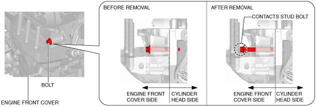
Engine Front Cover Disassembly Note (without electric variable valve timing)
-
Note
-
• Because the bolt shown in the figure contacts the stud bolt when the bolt is loosened, the bolt cannot be completely removed. However, the bolt comes out of the cylinder head so that the engine front cover can be removed.
1. Remove the engine front cover installation bolts.
2. Using a screwdriver wrapped in a cloth, peel the sealant away a little at a time, and remove the engine front cover.
Front Oil Seal Disassembly Note
1. Remove the oil seal using a flathead screwdriver with the tip protected by a clean cloth.
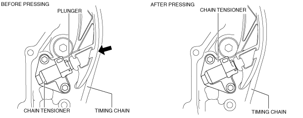
Chain Tensioner Disassembly Note (Chain Tensioner (Type A))
1. While moving the exhaust camshaft back and forth in the direction of the arrow using a wrench on the cast hexagon, press down the link plate of the timing chain tensioner using a precision screwdriver and release the plunger lock.
-
Note
-
• When moving the exhaust camshaft back and forth, the timing chain pushes the plunger in the chain tensioner making it easier to operate the link plate.
2. Push back the plunger slowly in the direction shown in the figure with the link plate still pushed down.
3. Remove the screwdriver from the link plate with the plunger still pushed down.
4. Release the force slightly from the plunger, and move it back and forth 2—3 mm {0.08—0.11 in}.
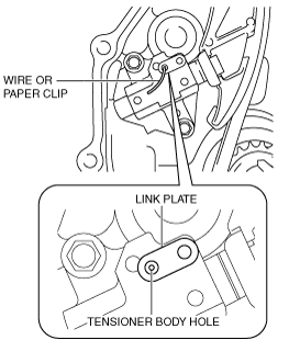
5. Insert a wire with an approx. diameter of 1.5 mm {0.059 in} or a paper clip where the link plate hole and the tensioner body hole overlap to secure the link plate and lock the plunger.
6. Remove the chain tensioner.
Chain Tensioner Disassembly Note (Chain Tensioner (Type B))
1. Insert a metal rod (diameter approx. 1.4 mm {0.055 in}, length approx. 55 mm {2.16 in}) into the hole in the body of the chain tensioner.
2. Press the resister ring and unlock the plunger.
3. Press the timing chain in the direction of the arrow and press in the chain tensioner plunger to the position where the groove and body hole are aligned.
4. With the plunger pressed in, further insert the metal rod set in (1) above.
-
Note
-
• The rod secures the plunger and releases the tension.
5. Loosen the power of the hand pressing the plunger and verify that the pressed-in rod does not move.
6. Remove the chain tensioner.
Oil Pump Driven Sprocket Disassembly Note (SKYACTIV-G 1.3, SKYACTIV-G 1.5, SKYACTIV-G 2.0)
1. Hold the crankshaft using the SST.
2. Remove the oil pump driven sprocket.
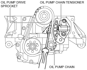
Oil Pump Chain Disassembly Note (SKYACTIV-G 2.5)
1. Hold the crankshaft using the SST.
2. Slightly loosen the balancer shaft sprocket and oil pump driven sprocket installation bolts.
-
Note
-
• At this stage, only loosen the installation bolts, do not remove it. Remove the bolt after removing the oil pump chain tensioner.
3. Set a cloth wrapped flathead screwdriver in the gap between oil pump drive sprocket and the oil pump chain as shown in the figure.
4. Move the screwdriver in the direction of the arrow and press the oil pump chain, and then press in the plunger of the oil pump chain tensioner.
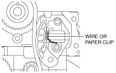
5. Insert a wire with an approx. diameter of 1.4 mm {0.055 in} or a paper clip into the body hole of the oil pump chain tensioner with the plunger pressed.
-
Note
-
• The wire or paper clip secures the plunger, and the tension can be released.
6. Remove the oil pump chain tensioner.
7. Remove the oil pump chain and balancer shaft sprocket as a single unit.
8. Remove the oil pump driven sprocket.