|
bfw2za00001095
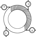
TRANSFER ASSEMBLY [FW6AX-EL]
id0316g1000300
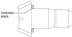
With tapered roller bearing
bfw2za00001095
|
|
1
|
Front carrier
|
|
2
|
Drive pinion gear
|
|
3
|
Spacer
|
|
4
|
Bearing inner race (front)
|
|
5
|
Bearing outer race (rear)
|
|
6
|
Bearing outer race (front)
|
|
7
|
Collapsible spacer
|
|
8
|
Drive pinion gear component
|
|
9
|
Bearing inner race (rear)
|
|
10
|
Oil seal
|
|
11
|
Companion flange component
|
|
12
|
Washer
|
|
13
|
Locknut
|
|
14
|
Ring gear shaft
|
|
15
|
Bearing inner race (LH)
|
|
16
|
Bearing inner race (RH)
|
|
17
|
Bearing outer race (LH)
|
|
18
|
Adjustment shim (LH)
|
|
19
|
Bearing outer race (RH)
|
|
20
|
Adjustment shim (RH)
|
|
21
|
Ring gear shaft component
|
|
22
|
Baffle plate
|
|
23
|
Drive gear case
|
|
24
|
Transfer oil seal (LH)
|
|
25
|
Transfer oil seal (RH) No.3
|
|
26
|
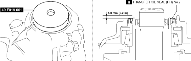
Transfer oil seal (RH) No.2
|
|
27
|
Transfer oil seal (RH) No.1
|
|
28
|
Breather
|
|
29
|
Drain plug, washer
|
|
30
|
Oil level plug, washer
|
With ball bearings/tandem ball bearings
bfw2za00001096
|
|
1
|
Front carrier
|
|
2
|
Drive pinion gear
|
|
3
|
Spacer
|
|
4
|
Bearing inner race (front)
|
|
5
|
Collapsible spacer
|
|
6
|
Bearing outer race (rear)
|
|
7
|
Bearing outer race (front)
|
|
8
|
Drive pinion gear component
|
|
9
|
Bearing inner race (rear)
|
|
10
|
Oil seal
|
|
11
|
Companion flange component
|
|
12
|
Washer
|
|
13
|
Locknut
|
|
14
|
Ring gear shaft
|
|
15
|
Ball bearing (LH)
|
|
16
|
Ball bearing (RH)
|
|
17
|
Adjustment shim (LH)
|
|
18
|
Adjustment shim (RH)
|
|
19
|
Ring gear shaft component
|
|
20
|
Baffle plate
|
|
21
|
Drive gear case
|
|
22
|
Transfer oil seal (LH)
|
|
23
|
Transfer oil seal (RH) No.3
|
|
24
|
Transfer oil seal (RH) No.2
|
|
25
|
Transfer oil seal (RH) No.1
|
|
26
|
Breather
|
|
27
|
Drain plug, washer
|
|
28
|
Oil level plug, washer
|
1. Clean the contact surfaces of the front carrier and drive gear case.
2. Assemble the drive pinion gear component and companion flange to the front carrier using the following procedure.
bfw2za00001097
|
Spacer table
|
Identification number |
Thickness (mm {in}) |
Identification number |
Thickness (mm {in}) |
|---|---|---|---|
|
08
|
3.080 {0.1213}
|
29
|
3.290 {0.1295}
|
|
09
|
3.095 {0.1219}
|
30
|
3.305 {0.1301}
|
|
11
|
3.110 {0.1224}
|
32
|
3.320 {0.1307}
|
|
12
|
3.125 {0.1230}
|
33
|
3.335 {0.1313}
|
|
14
|
3.140 {0.1236}
|
35
|
3.350 {0.1319}
|
|
15
|
3.155 {0.1242}
|
36
|
3.365 {0.1325}
|
|
17
|
3.170 {0.1248}
|
38
|
3.380 {0.1331}
|
|
18
|
3.185 {0.1254}
|
39
|
3.395 {0.1337}
|
|
20
|
3.200 {0.1260}
|
41
|
3.410 {0.1343}
|
|
21
|
3.215 {0.1266}
|
42
|
3.425 {0.1348}
|
|
23
|
3.230 {0.1272}
|
44
|
3.440 {0.1354}
|
|
24
|
3.245 {0.1278}
|
45
|
3.455 {0.1360}
|
|
26
|
3.260 {0.1283}
|
47
|
3.470 {0.1366}
|
|
27
|
3.275 {0.1289}
|
−
|
−
|
bfw2za00001098
|
bfw2za00001099
|
bfw2za00001100
|
bfw3ja00000877
|
bfw3ja00000878
|
bfw3ja00000879
|
bfw3ja00000877
|
bfw3ja00000878
|
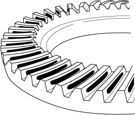
3. Assemble the ring gear shaft component to the front carrier using the following procedure.
bfw2za00001101
|
bfw3ja00000525
|
bfw2za00001102
|
bfw3ja00000527
|
bfw2za00001103
|
bfw2za00001104
|
bfw2za00001105
|
bfw2za00001106
|
Adjustment shim table (With tapered roller bearing)
|
Identification number |
Thickness (mm {in}) |
Identification number |
Thickness (mm {in}) |
|---|---|---|---|
|
449
|
4.490 {0.1768}
|
503
|
5.030 {0.1980}
|
|
452
|
4.520 {0.1780}
|
506
|
5.060 {0.1992}
|
|
455
|
4.550 {0.1791}
|
509
|
5.090 {0.2004}
|
|
458
|
4.580 {0.1803}
|
512
|
5.120 {0.2016}
|
|
461
|
4.610 {0.1815}
|
515
|
5.150 {0.2028}
|
|
464
|
4.640 {0.1827}
|
518
|
5.180 {0.2039}
|
|
467
|
4.670 {0.1839}
|
521
|
5.210 {0.2051}
|
|
470
|
4.700 {0.1850}
|
524
|
5.240 {0.2063}
|
|
473
|
4.730 {0.1862}
|
527
|
5.270 {0.2075}
|
|
476
|
4.760 {0.1874}
|
530
|
5.300 {0.2087}
|
|
479
|
4.790 {0.1886}
|
533
|
5.330 {0.2098}
|
|
482
|
4.820 {0.1898}
|
536
|
5.360 {0.2110}
|
|
485
|
4.850 {0.1909}
|
539
|
5.390 {0.2122}
|
|
488
|
4.880 {0.1921}
|
542
|
5.420 {0.2134}
|
|
491
|
4.910 {0.1933}
|
545
|
5.450 {0.2146}
|
|
494
|
4.940 {0.1945}
|
548
|
5.480 {0.2157}
|
|
497
|
4.970 {0.1957}
|
551
|
5.510 {0.2169}
|
|
500
|
5.000 {0.1969}
|
−
|
−
|
Adjustment shim table (With ball bearing/tandem ball bearing)
|
Identification number |
Thickness (mm {in}) |
Identification number |
Thickness (mm {in}) |
|---|---|---|---|
|
6490
|
6.490 {0.2555}
|
7000
|
7.000 {0.2756}
|
|
6505
|
6.505 {0.2561}
|
7015
|
7.015 {0.2762}
|
|
6520
|
6.520 {0.2567}
|
7030
|
7.030 {0.2768}
|
|
6535
|
6.535 {0.2573}
|
7045
|
7.045 {0.2774}
|
|
6550
|
6.550 {0.2579}
|
7060
|
7.060 {0.2780}
|
|
6565
|
6.565 {0.2585}
|
7075
|
7.075 {0.2785}
|
|
6580
|
6.580 {0.2591}
|
7090
|
7.090 {0.2791}
|
|
6595
|
6.595 {0.2596}
|
7105
|
7.105 {0.2797}
|
|
6610
|
6.610 {0.2602}
|
7120
|
7.120 {0.2803}
|
|
6625
|
6.625 {0.2608}
|
7135
|
7.135 {0.2809}
|
|
6640
|
6.640 {0.2614}
|
7150
|
7.150 {0.2815}
|
|
6655
|
6.655 {0.2620}
|
7165
|
7.165 {0.2821}
|
|
6670
|
6.670 {0.2626}
|
7180
|
7.180 {0.2827}
|
|
6685
|
6.685 {0.2632}
|
7195
|
7.195 {0.2833}
|
|
6700
|
6.700 {0.2638}
|
7210
|
7.210 {0.2839}
|
|
6715
|
6.715 {0.2644}
|
7225
|
7.225 {0.2844}
|
|
6730
|
6.730 {0.2650}
|
7240
|
7.240 {0.2850}
|
|
6745
|
6.745 {0.2656}
|
7255
|
7.255 {0.2856}
|
|
6760
|
6.760 {0.2661}
|
7270
|
7.270 {0.2862}
|
|
6775
|
6.775 {0.2667}
|
7285
|
7.285 {0.2868}
|
|
6790
|
6.790 {0.2673}
|
7300
|
7.300 {0.2874}
|
|
6805
|
6.805 {0.2679}
|
7315
|
7.315 {0.2880}
|
|
6820
|
6.820 {0.2685}
|
7330
|
7.330 {0.2886}
|
|
6835
|
6.835 {0.2691}
|
7345
|
7.345 {0.2892}
|
|
6850
|
6.850 {0.2697}
|
7360
|
7.360 {0.2898}
|
|
6865
|
6.865 {0.2703}
|
7375
|
7.375 {0.2904}
|
|
6880
|
6.880 {0.2709}
|
7390
|
7.390 {0.2909}
|
|
6895
|
6.895 {0.2715}
|
7405
|
7.405 {0.2915}
|
|
6910
|
6.910 {0.2720}
|
7420
|
7.420 {0.2921}
|
|
6925
|
6.925 {0.2726}
|
7435
|
7.435 {0.2927}
|
|
6940
|
6.940 {0.2732}
|
7450
|
7.450 {0.2933}
|
|
6955
|
6.955 {0.2738}
|
7465
|
7.465 {0.2939}
|
|
6970
|
6.970 {0.2744}
|
7480
|
7.480 {0.2945}
|
|
6985
|
6.985 {0.2750}
|
7495
|
7.495 {0.2951}
|
|
−
|
−
|
7510
|
7.510 {0.2957}
|
bfw2za00001107
|
bfw2za00001108
|
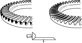
4. Perform the ring gear and drive pinion backlash adjustment.
bfw3ja00000386
|
bfw3ja00000387
|
Adjustment shim table (With tapered roller bearing)
|
Identification number |
Thickness (mm {in}) |
Identification number |
Thickness (mm {in}) |
|---|---|---|---|
|
449
|
4.490 {0.1768}
|
503
|
5.030 {0.1980}
|
|
452
|
4.520 {0.1780}
|
506
|
5.060 {0.1992}
|
|
455
|
4.550 {0.1791}
|
509
|
5.090 {0.2004}
|
|
458
|
4.580 {0.1803}
|
512
|
5.120 {0.2016}
|
|
461
|
4.610 {0.1815}
|
515
|
5.150 {0.2028}
|
|
464
|
4.640 {0.1827}
|
518
|
5.180 {0.2039}
|
|
467
|
4.670 {0.1839}
|
521
|
5.210 {0.2051}
|
|
470
|
4.700 {0.1850}
|
524
|
5.240 {0.2063}
|
|
473
|
4.730 {0.1862}
|
527
|
5.270 {0.2075}
|
|
476
|
4.760 {0.1874}
|
530
|
5.300 {0.2087}
|
|
479
|
4.790 {0.1886}
|
533
|
5.330 {0.2098}
|
|
482
|
4.820 {0.1898}
|
536
|
5.360 {0.2110}
|
|
485
|
4.850 {0.1909}
|
539
|
5.390 {0.2122}
|
|
488
|
4.880 {0.1921}
|
542
|
5.420 {0.2134}
|
|
491
|
4.910 {0.1933}
|
545
|
5.450 {0.2146}
|
|
494
|
4.940 {0.1945}
|
548
|
5.480 {0.2157}
|
|
497
|
4.970 {0.1957}
|
551
|
5.510 {0.2169}
|
|
500
|
5.000 {0.1969}
|
−
|
−
|
Adjustment shim table (With ball bearing/tandem ball bearing)
|
Identification number |
Thickness (mm {in}) |
Identification number |
Thickness (mm {in}) |
|---|---|---|---|
|
6490
|
6.490 {0.2555}
|
7000
|
7.000 {0.2756}
|
|
6505
|
6.505 {0.2561}
|
7015
|
7.015 {0.2762}
|
|
6520
|
6.520 {0.2567}
|
7030
|
7.030 {0.2768}
|
|
6535
|
6.535 {0.2573}
|
7045
|
7.045 {0.2774}
|
|
6550
|
6.550 {0.2579}
|
7060
|
7.060 {0.2780}
|
|
6565
|
6.565 {0.2585}
|
7075
|
7.075 {0.2785}
|
|
6580
|
6.580 {0.2591}
|
7090
|
7.090 {0.2791}
|
|
6595
|
6.595 {0.2596}
|
7105
|
7.105 {0.2797}
|
|
6610
|
6.610 {0.2602}
|
7120
|
7.120 {0.2803}
|
|
6625
|
6.625 {0.2608}
|
7135
|
7.135 {0.2809}
|
|
6640
|
6.640 {0.2614}
|
7150
|
7.150 {0.2815}
|
|
6655
|
6.655 {0.2620}
|
7165
|
7.165 {0.2821}
|
|
6670
|
6.670 {0.2626}
|
7180
|
7.180 {0.2827}
|
|
6685
|
6.685 {0.2632}
|
7195
|
7.195 {0.2833}
|
|
6700
|
6.700 {0.2638}
|
7210
|
7.210 {0.2839}
|
|
6715
|
6.715 {0.2644}
|
7225
|
7.225 {0.2844}
|
|
6730
|
6.730 {0.2650}
|
7240
|
7.240 {0.2850}
|
|
6745
|
6.745 {0.2656}
|
7255
|
7.255 {0.2856}
|
|
6760
|
6.760 {0.2661}
|
7270
|
7.270 {0.2862}
|
|
6775
|
6.775 {0.2667}
|
7285
|
7.285 {0.2868}
|
|
6790
|
6.790 {0.2673}
|
7300
|
7.300 {0.2874}
|
|
6805
|
6.805 {0.2679}
|
7315
|
7.315 {0.2880}
|
|
6820
|
6.820 {0.2685}
|
7330
|
7.330 {0.2886}
|
|
6835
|
6.835 {0.2691}
|
7345
|
7.345 {0.2892}
|
|
6850
|
6.850 {0.2697}
|
7360
|
7.360 {0.2898}
|
|
6865
|
6.865 {0.2703}
|
7375
|
7.375 {0.2904}
|
|
6880
|
6.880 {0.2709}
|
7390
|
7.390 {0.2909}
|
|
6895
|
6.895 {0.2715}
|
7405
|
7.405 {0.2915}
|
|
6910
|
6.910 {0.2720}
|
7420
|
7.420 {0.2921}
|
|
6925
|
6.925 {0.2726}
|
7435
|
7.435 {0.2927}
|
|
6940
|
6.940 {0.2732}
|
7450
|
7.450 {0.2933}
|
|
6955
|
6.955 {0.2738}
|
7465
|
7.465 {0.2939}
|
|
6970
|
6.970 {0.2744}
|
7480
|
7.480 {0.2945}
|
|
6985
|
6.985 {0.2750}
|
7495
|
7.495 {0.2951}
|
|
−
|
−
|
7510
|
7.510 {0.2957}
|
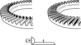
5. Perform the drive pinion gear and ring gear shaft tooth contact inspection using the following procedure.
bfw3ja00000884
|
bfw3ja00000885
|
bfw3ja00000886
|
Spacer table
|
Identification number |
Thickness (mm {in}) |
Identification number |
Thickness (mm {in}) |
|---|---|---|---|
|
08
|
3.080 {0.1213}
|
29
|
3.290 {0.1295}
|
|
09
|
3.095 {0.1219}
|
30
|
3.305 {0.1301}
|
|
11
|
3.110 {0.1224}
|
32
|
3.320 {0.1307}
|
|
12
|
3.125 {0.1230}
|
33
|
3.335 {0.1313}
|
|
14
|
3.140 {0.1236}
|
35
|
3.350 {0.1319}
|
|
15
|
3.155 {0.1242}
|
36
|
3.365 {0.1325}
|
|
17
|
3.170 {0.1248}
|
38
|
3.380 {0.1331}
|
|
18
|
3.185 {0.1254}
|
39
|
3.395 {0.1337}
|
|
20
|
3.200 {0.1260}
|
41
|
3.410 {0.1343}
|
|
21
|
3.215 {0.1266}
|
42
|
3.425 {0.1348}
|
|
23
|
3.230 {0.1272}
|
44
|
3.440 {0.1354}
|
|
24
|
3.245 {0.1278}
|
45
|
3.455 {0.1360}
|
|
26
|
3.260 {0.1283}
|
47
|
3.470 {0.1366}
|
|
27
|
3.275 {0.1289}
|
−
|
−
|
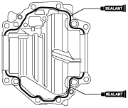
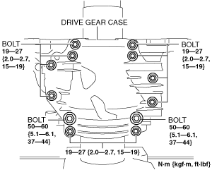
6. Assemble the drive gear case to the front carrier using the following procedure.
bfw2za00001109
|
bfw2za00001107
|
bfw3ja00000888
|
bfw2za00001110
|
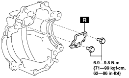
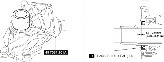
7. Assemble the transfer oil seal to the transfer using the following procedure.
bfw2za00001111
|
bfw2za00001112
|
bfw2za00001113
|
bfw2za00001114
|
bfw2za00001115
|
8. Assemble a new breather.
9. Assemble a new washer and drain plug.
10. Assemble a new washer and oil level plug.