LOW AND REVERSE BRAKE CLEARANCE MEASUREMENT/ADJUSTMENT
id051700664700
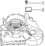
Preparation Before Servicing
1. Print out the measurement/adjustment value input sheet. (See MEASUREMENT/ADJUSTMENT VALUE INPUT SHEET [EW6A-EL/EW6AX-EL].)(See MEASUREMENT/ADJUSTMENT VALUE INPUT SHEET [FW6A-EL/FW6AX-EL].)
-
Note
-
• When performing the measurement/adjustment, input the measured and calculated values into the measurement/adjustment value input sheet.
• When performing the other measurements/adjustments, if the measurement/adjustment value input sheet has been printed out, use the printed sheet.
Low and Reverse Brake Clearance Measurement
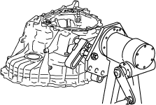
1. Rotate and adjust the rotation handle of the engine stand so that the end cover side is facing upward.
-
Caution
-
• To reduce error during the low and reverse brake clearance measurement, adjust so that the alignment surface of the transaxle case with the end cover is level.
2. Assemble the snap ring using the following procedure:
-
Note
-
• Snap ring size: Outer diameter approx. 198.0 mm {7.795 in}
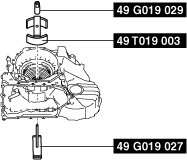
- (1) Install the SSTs.
-
- (2) Tighten the SST (49 G019 029) until the snap ring groove of the transaxle case comes out.
-
-
Caution
-
• If the SST (49 G019 029) is tightened with excessive force, surrounding parts could be damaged. Stop tightening the SST when the snap ring groove of the transaxle case comes out.
-
Note
-
• Lock the SST (49 G019 027) against rotation using a flathead screwdriver and tighten the SST (49 G019 029).
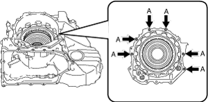
A :Snap ring groove
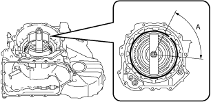
- (3) Assemble the snap ring to the position shown in the figure.
-
-
Caution
-
• Assemble the snap ring so that the end gap of the snap ring is in the area shown in the figure.
• After assembling the snap ring, verify that the snap ring is securely inserted into the bottom of the snap ring groove.
A :End gap of snap ring assembly area
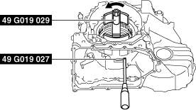
- (4) Loosen the SST (49 G019 029) and remove the SSTs.
-
-
Note
-
• Lock the SST (49 G019 027) against rotation using a flathead screwdriver and loosen the SST (49 G019 029).
3. Set the measuring instrument to the transaxle case using the following procedure.
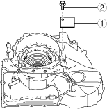
- (1) Install the steel plate for securing the magnetic stand using the procedure shown in the figure.
-
-
Caution
-
• If the bolt is tightened with excessive force when installing the steel plate, the alignment surface of the end cover with the transaxle case could be damaged. Tighten the bolt so that the steel plate does not move during low and reverse brake clearance measurement.
• To prevent damage to the parts, the bolt holes in the transaxle case which are used for securing the steel plate are the penetrated bolt holes shown in the figure.
-
Note
-
• When installing the steel plate to the transaxle case, use a bolt (M8×1.25).
• Use a bolt length in which the bolt end comes out of the transaxle case bolt hole but does not contact the transaxle case.
• Because it is necessary to measure the low and reverse brake clearance in four locations (each separated by 90°), change the steel plate installation position to the area of the bolt installation position shown in the figure then install the steel plate to a position which facilitates measurement.
A :Bolt installation position for steel plate installation
|
1
|
Steel plate (for securing magnetic stand)
|
|
2
|
Bolt (M8×1.25)*
|
* :Use a bolt length in which the bolt end comes out of the transaxle case bolt hole but does not contact the transaxle case.
-
Steel plate installation bolt tightening torque
-
15 N·m {1.5 kgf·m, 11 ft·lbf} or less (tighten so that steel plate does not move during low and reverse brake clearance measurement)
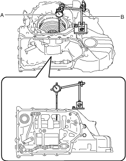
- (2) Set the dial gauge and magnetic stand as shown in the figure.
-
-
Caution
-
• To reduce error during the low and reverse brake clearance measurement, set the dial gauge so that it is perpendicular to the alignment surface of the transaxle case with the end cover.
A :Dial gauge
B :Magnetic stand
- (3) Set the dial gauge end to the low and reverse brake piston.
-
-
Note
-
• Measure the stroke amount of the low and reverse brake piston as the low and reverse brake clearance.
A :Area in which dial gauge end is set
4. Measure the low and reverse brake clearance using the following procedure:
- (1) Blow compressed air into the oil passage shown in the figure and verify the operation condition of the low and reverse brake (approx. 3 times).
-
-
Warning
-
• Always wear protective eye wear when using the air compressor. Otherwise, ATF or dirt particles blown off by the air compressor could get into the eyes.
-
Caution
-
• To prevent damage to parts, always use an air compressor which is adjusted to the indicated pressure.
-
Compressed air pressure
-
0.39—0.44 MPa {4.0—4.4 kgf/cm2, 57—63 psi}
- (2) Blow compressed air into the oil passage shown in the figure and operate the low and reverse brake piston to read the value when the dial gauge is stabilized.
-
-
Warning
-
• Always wear protective eye wear when using the air compressor. Otherwise, ATF or dirt particles blown off by the air compressor could get into the eyes.
-
Caution
-
• To prevent damage to parts, always use an air compressor which is adjusted to the indicated pressure.
-
Compressed air pressure
-
0.39—0.44 MPa {4.0—4.4 kgf/cm2, 57—63 psi}
- (3) Input the dial gauge value, which was read while the low and reverse brake piston was operating, into the measurement/adjustment value input sheet.
-
- (4) Release the compressed air and read the dial gauge value without the low and reverse brake piston operating.
-
- (5) Input the dial gauge value, which was read without the low and reverse brake piston operating, into the measurement/adjustment value sheet.
-
- (6) Perform the following calculation to calculate the low and reverse brake clearance.
-
-
Low and reverse brake clearance = A - B
-
A: Dial gauge value with low and reverse brake piston operating
B: Dial gauge value without low and reverse brake piston operating
-
Note
-
Example
A: Dial gauge value with low and reverse brake piston operating is 2.470 mm {0.09724 in}
B: Dial gauge value without low and reverse brake piston operating is 0.595 mm {0.02343 in}
Low and reverse brake clearance = 2.470 mm {0.09724 in} - 0.595 mm {0.02343 in}= 1.875 mm {0.07382 in}
- (7) Input the calculated low and reverse brake clearance into the measurement/adjustment value sheet.
-
- (8) Measure the low and reverse brake clearance in four locations (each separated by 90°) and calculate the average value of the low and reverse brake clearance.
-
-
Note
-
• Change the set positions of the dial gauge and magnetic stand and measure the low and reverse brake clearance in four locations (each separated by 90°).
- (9) Input the average value of the calculated low and reverse brake clearance into the measurement/adjustment value sheet.
-
- (10) Verify that the average value of the low and reverse brake clearance satisfies the specification.
-
-
Specification
-
1.650—1.850 mm {0.06497—0.07283 in}
-
5. Remove the dial gauge and magnetic stand.
A :Dial gauge
B :Magnetic stand
6. Remove the steel plate for securing the magnetic stand using the procedure shown in the figure.
|
1
|
Bolt
|
|
2
|
Steel plate (for securing magnetic stand)
|
Low and Reverse Brake Clearance Adjustment
1. Remove the dial gauge and magnetic stand.
A :Dial gauge
B :Magnetic stand
2. Remove the steel plate for securing the magnetic stand using the procedure shown in the figure.
|
1
|
Bolt
|
|
2
|
Steel plate (for securing magnetic stand)
|
3. Remove the snap ring using the following procedure:
- (1) Install the SSTs.
-
- (2) Tighten the SST (49 G019 029) until there is no longer any spring force from the springs and retainer component applied to the snap ring.
-
-
Caution
-
• If the SST (49 G019 029) is tightened with excessive force, surrounding parts could be damaged. Stop tightening if a gap appears between the snap ring and one-way clutch
-
Note
-
• Lock the SST (49 G019 027) against rotation using a flathead screwdriver and tighten the SST (49 G019 029).
A :Snap ring
B :One-way clutch
C :Gap
- (3) Remove the snap ring.
-
4. Measure the thickness of the removed snap ring.
-
Note
-
• Recommended measuring instrument: Micrometer
5. Input the measured snap ring thickness into the measurement/adjustment value input sheet.
6. Select the appropriate snap ring from the following table:
|
Range*
|
Selected snap ring thickness
|
|
Exceeds 4.500 mm {0.1772 in}, 4.600 mm {0.1811 in} or less
|
2.8 mm {0.110 in}
|
|
Exceeds 4.400 mm {0.1732 in}, 4.500 mm {0.1772 in} or less
|
2.7 mm {0.106 in}
|
|
Exceeds 4.300 mm {0.1693 in}, 4.400 mm {0.1732 in} or less
|
2.6 mm {0.102 in}
|
|
Exceeds 4.200 mm {0.1654 in}, 4.300 mm {0.1693 in} or less
|
2.5 mm {0.098 in}
|
|
Exceeds 4.100 mm {0.1614 in}, 4.200 mm {0.1654 in} or less
|
2.4 mm {0.094 in}
|
|
Exceeds 4.000 mm {0.1575 in}, 4.100 mm {0.1614 in} or less
|
2.3 mm {0.091 in}
|
|
Exceeds 3.900 mm {0.1535 in}, 4.000 mm {0.1575 in} or less
|
2.2 mm {0.087 in}
|
|
Exceeds 3.800 mm {0.1496 in}, 3.900 mm {0.1535 in} or less
|
2.1 mm {0.083 in}
|
|
Exceeds 3.700 mm {0.1457 in}, 3.800 mm {0.1496 in} or less
|
2.0 mm {0.079 in}
|
|
Exceeds 3.600 mm {0.1417 in}, 3.700 mm {0.1457 in} or less
|
1.9 mm {0.075 in}
|
|
Exceeds 3.500 mm {0.1378 in}, 3.600 mm {0.1417 in} or less
|
1.8 mm {0.071 in}
|
* :The range is the sum of the average value of the low and reverse brake clearance and the thickness value of the removed snap ring.
-
Range = D + G
-
D: Average value of low and reverse brake clearance
G: Thickness of removed snap ring
-
Note
-
Example
D: Average value of low and reverse brake clearance is 1.879 mm {0.07398 in}
G: Thickness of removed snap ring is 2.305 mm {0.09075 in}
Range = 1.879 mm {0.07398 in}+ 2.305 mm {0.09075 in}= 4.184 mm {0.16472 in}, the selected snap ring has a thickness of 2.6 mm {0.102 in}.
7. Assemble the selected snap ring using the following procedure:
-
Note
-
• Snap ring size: Outer diameter approx. 198.0 mm {7.795 in}
- (1) Tighten the SST (49 G019 029) until the snap ring groove of the transaxle case comes out.
-
-
Caution
-
• If the SST (49 G019 029) is tightened with excessive force, surrounding parts could be damaged. Stop tightening the SST when the snap ring groove of the transaxle case comes out.
-
Note
-
• Lock the SST (49 G019 027) against rotation using a flathead screwdriver and tighten the SST (49 G019 029).
A :Snap ring groove
- (2) Assemble the snap ring to the position shown in the figure.
-
-
Caution
-
• Assemble the snap ring so that the end gap of the snap ring is in the area shown in the figure.
• After assembling the snap ring, verify that the snap ring is securely inserted into the bottom of the snap ring groove.
A :End gap of snap ring assembly area
- (3) Loosen the SST (49 G019 029) and remove the SSTs.
-
-
Note
-
• Lock the SST (49 G019 027) against rotation using a flathead screwdriver and loosen the SST (49 G019 029).
8. Perform the low and reverse brake clearance measurement from Step 3. (See Low and Reverse Brake Clearance Measurement.)