FOREWORD
id051700660100
-
Warning
-
• The engine stand has a self-lock mechanism, however, if the transfer is in a tilted condition, the self-lock mechanism could become inoperative. Under this condition, the transfer could rotate unexpectedly and cause injury. Therefore, do not hold the transfer in a tilted condition. When turning the transfer, always grasp the rotation handle firmly and be careful to prevent the transfer from moving unexpectedly.
• Always wear protective eye wear when using the air compressor. Otherwise, ATF or dirt particles blown off by the air compressor could get into the eyes.
-
Note
-
• Differences in part shapes between GW6A-EL and GW6AX-EL are as follows: This manual was produced based on GW6A-EL, and the descriptions were divided into GW6A-EL and GW6AX-EL only if differences in the servicing method between GW6A-EL and GW6AX-EL occur.
-
― Oil seal (Converter housing side of differential)
Operation Cautions
• Prevent foreign matter penetration into the transaxle.
-
― Clean the outside of the transaxle using steam or degreaser before disassembly.
-
Caution
-
• If the outside of the transaxle is cleaned, plug the position shown in the figure with packing tape and be careful that foreign matter, water, or degreaser does not penetrate the transaxle and connector.
A: Breather pipe
B: Control valve body connector
C: Electric AT oil pump connector (only vehicles with i-stop)
D: Connector bolt (only vehicles with oil cooler No.2)
E: Oil cooler
F: Oil seal
G: Oil seal
― To prevent dust penetration into the transaxle, perform the procedure in a dust free room.
― To prevent lint penetration into the transaxle, perform the procedure with bare hands or wearing vinyl gloves. Do not use cotton gloves or rag.
― Organize and store the disassembled parts to protect them from dust or dirt.
― Before assembly, verify that each part is clean and dried.
― Clean off remaining old sealant before applying new sealant.
― Do not clean the following parts, otherwise foreign matter or degreaser may penetrate the oil passage or internal part:
-
• Control valve body (including the following parts:)
— ON/OFF solenoid
— Oil pressure switch A
— Oil pressure switch B
— Coupler component
• Electric AT oil pump (only vehicles with i-stop)
• Disassemble while looking for damage, cracks, deformation, scratches, and the assembly condition of parts.
• When servicing, be very careful not to get injured by the edges of parts.
• If ATF is dripping on the floor, wipe it off immediately because a slippery floor is dangerous.
• If the connecting part of a light-alloy part for the transaxle case is disassembled, disassemble it by lightly tapping using a plastic hammer. Do not twist the part or use a flathead screwdriver.
• Thoroughly inspect the foreign matter found in the transaxle or on the magnet to help determine the transaxle condition.
• If using a vise, secure the component using a protective plate (aluminum plate) to prevent component damage.
• Be very careful when handling electronic components.
-
― If a connector is disconnected, do not pull the wiring harness. Pull the connector out straight after releasing the lock.
― Do not touch the terminal as the connector terminal could be damaged.
― Verify that there is no foreign matter adhering to the connector before connecting the connector.
― When connecting a connector, insert it straight until it is securely locked.
― Do not apply impact to electronic components. Replace with a new component if one was dropped or received an impact.
• To prevent damage to parts, always use an air compressor which is adjusted to the indicated pressure.
• Always use ATF FZ for the ATF.
• Always use silicone sealant TB1217E for sealant.
• If a drive plate is replaced with a new one, immerse it in ATF (ATF FZ) for 2 hours or more to permeate the facing with ATF.
• Do not clean the drive plate using degreaser.
• Do not clean the internal part of the torque converter using degreaser.
• Do not clean the internal part of the oil cooler using degreaser.
• Do not clean aluminum and rubber parts using an alkaline agent.
• Do not clean rubber parts using white gasoline and kerosene.
• When assembling a part which is designated for replacement with every disassembly, always use a new part.
• Replace the damaged or deformed snap ring with a new one.
Required SSTs, Measuring Instruments, and Parts for Servicing
• Measuring instrument
-
― Vernier caliper
― Micrometer
― Cylinder gauge or caliper gauge
― Dial gauge
― Magnetic stand
― Depth gauge
― Depth micrometer
― Straight edge ruler (two of the same type)
― Thickness gauge
― Torque wrench
• Part
|
Part name
|
Part number
|
Quantity
|
Comment
|
|
Bolt
|
9YA02 1440
|
3
|
M14×1.5 bolt, length 100 mm {3.94 in} possible
|
|
Bolt
|
9YA02 1015
|
1
|
M10×1.5 bolt, length 35 mm {1.4 in} possible
|
|
Bolt
|
9YA02 A220
|
4
|
M12×1.75 bolt, length 40 mm {1.6 in} possible
|
|
Bolt
|
—
|
1
|
M10 bolt, length approx. 60 mm {2.4 in}
|
|
Nut
|
—
|
1
|
M10 nut (pitch matching above M10 bolt)
|
|
Bolt
|
—
|
1
|
M8 bolt, length approx. 50 mm {2.0 in}
|
|
Nut
|
—
|
1
|
M8 nut (pitch matching above M8 bolt)
|
|
Bolt
|
—
|
1
|
M8×1.25 bolt, length approx. 20 mm {0.79 in}
|
|
Snap ring
|
FZ01 19 469
|
1
|
Measurement/adjustment for R-3-5 brake clearance
|
|
Shim
|
FZ01 19 2L1
|
1
|
Measurement/adjustment for total end play
|
|
ATF
|
—
|
—
|
ATF FZ
|
|
Sealant
|
—
|
—
|
Silicone sealant TB1217E
|
After Service Precaution
• After installing the overhauled transaxle to the vehicle, perform the procedure in the following order.
-
Note
-
• For the service procedure, verify the Workshop Manual.
-
1. TCM configuration
-
Caution
-
• Perform the TCM configuration only if the control valve body is replaced.
In addition, because there are vehicle models which require/do not require the TCM configuration even if the control valve body is replaced, verify the Workshop Manual.
2. Initial learning
3. Mechanical system test
4. Road test
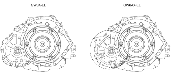 bgw3ja00000642― Differential gear case
 bgw2za00000003― Oil seal (Converter housing side of differential)
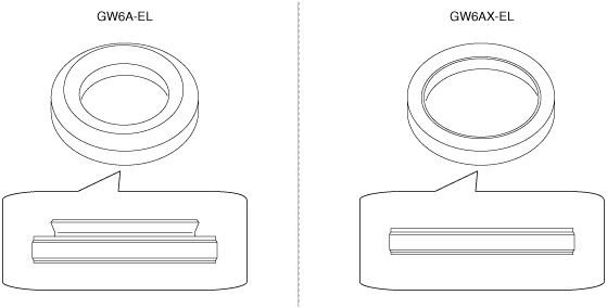 bgw3ja00000004