RING GEAR AND DIFFERENTIAL DISASSEMBLY


id051700661100


Structural View

bgw2za00000122

1
Tapered roller bearing (transaxle case side)
2
Tapered roller bearing (converter housing side)
3
12 bolts
4
Ring gear
5
Roll pin
6
Pinion shaft
7
Pinion gear
8
Thrust washer
9
Side gear
10
Thrust washer
11
Differential gear case


Disassembly Procedure

1.  Perform the following inspection:

Caution
•  If there is no malfunction based on the results of the inspection, it is not necessary to disassemble the ring gear and differential.
•  Visual inspection of parts (See VISUAL INSPECTION OF PARTS)
•  Ring gear and differential inspection (See RING GEAR AND DIFFERENTIAL INSPECTION)
•  If there is a malfunction, disassemble the ring gear and differential and replace the malfunctioning part with a new part.

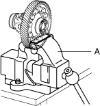
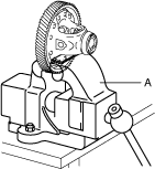
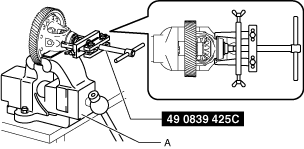
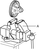
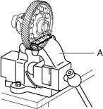
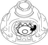
2.  Remove the tapered roller bearing (transaxle case side) using the following procedure:

(1)  Secure the ring gear and differential in a vise.
Caution
•  Insert a protective plate between the vise and the part so as not to damage the part.
bgw3ja00000208
A  :Vise
(2)  Remove the tapered roller bearing (transaxle case side) using the SST.
bgw2za00000205
A  :Vise
bgw3ja00000210
(3)  Remove the ring gear and differential from the vise.
bgw3ja00000211
A  :Vise

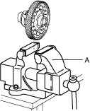
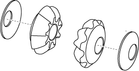
3.  Remove the tapered roller bearing (converter housing side) using the following procedure:

(1)  Secure the ring gear and differential in a vise.
Caution
•  Insert a protective plate between the vise and the part so as not to damage the part.
bgw3ja00000212
A  :Vise
(2)  Remove the tapered roller bearing (converter housing side) using the SST.
bgw2za00000206
A  :Vise
bgw3ja00000214
(3)  Remove the ring gear and differential from the vise.
bgw3ja00000215
A  :Vise

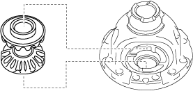
4.  Remove the ring gear using the following procedure:

bgw3ja00000216

1
12 bolts
2
Ring gear

(1)  Secure the ring gear and differential in a vise.
Caution
•  Insert a protective plate between the vise and the part so as not to damage the part.
bgw3ja00000217
A  :Vise
(2)  Loosen the bolts shown in the figure.
Caution
•  If the bolts are removed, the differential may separate from the ring gear and fall off. Only loosen the bolts but do not remove them.
Note
•  Change the securing position of the ring gear and differential with the vise and loosen all of the bolts shown in the figure.
bgw3ja00000218
(3)  Remove the ring gear and differential from the vise.
bgw3ja00000219
A  :Vise
(4)  Remove the bolts shown in the figure.
bgw3ja00000218
(5)  Lightly tap the ring gear with a plastic hammer and remove the ring gear.
bgw3ja00000220
bgw3ja00000221

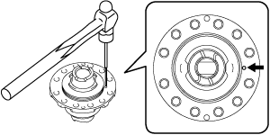
5.  Remove the roll pin shown in the figure using a pin punch.

Note
•  Use a pin punch with an end outer diameter of 3 mm {0.119 in} or more, and within 4 mm {0.157 in} and an end length of 60 mm {2.4 in} or more.
bgw3ja00000222
bgw2za00000207

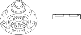
6.  Remove the pinion shaft.

bgw3ja00000224

7.  Remove the pinion gears using the following procedure:

(1)  Rotate the pinion gears as shown in the figure.
bgw3ja00000225
(2)  Remove the pinion gears.
bgw3ja00000226

8.  Remove the thrust washers from the pinion gears.

azzjjw00001492

9.  Remove the side gears.

bgw3ja00000227

10.  Remove the thrust washers from the side gears.

azzjjw00001494

11.  Clean the disassembled parts. (See AUTOMATIC TRANSAXLE CLEANING.)