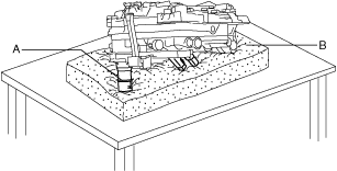
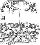
CONTROL VALVE BODY DISASSEMBLY


id051700661400


Structural View

azzjjw00001499

1
8 bolts
2
Coupler component
3
Bolt
4
ON/OFF solenoid
5
3 bolts
6
Oil pressure switch B
7
3 bolts
8
Oil pressure switch A


Disassembly Procedure

Caution
•  Disassemble the control valve body and replace the malfunctioning part only if there is a malfunction in the control valve body determined by the troubleshooting procedure and using the vehicle diagnostic tester (M-MDS).
However, if there is a malfunction in the parts other than the following, replace the control valve body with a new one because the parts other than the following are not shipped from the factory as a single component.
―  ON/OFF solenoid
―  Oil pressure switch A
―  Oil pressure switch B
―  Coupler component
•  Do not drop or apply an impact to the control valve body. Replace the control valve body with a new one if it was dropped or received an impact.
•  Placing the TCM side pointed downward on a workbench directly could damage the TCM. If the TCM side is placed pointed downward, place the control valve body on an impact-absorbing material so that the TCM does not contact the workbench directly.
azzjjw00001500
A: TCM
B: Impact-absorbing material

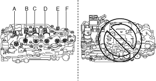
1.  Remove the coupler component using the following procedure.

azzjjw00000900

1
8 bolts
2
Coupler component

(1)  Disconnect the connector shown in the figure.
Caution
•  If a connector is disconnected, do not pull the wiring harness. Pull the connector out straight after releasing the lock.
azzjjw00000896
azzjjw00000897
(2)  Place the control valve body with the TCM side pointing downward on an impact-absorbing material as shown in the figure.
Caution
•  Placing the TCM side pointed downward on a workbench directly could damage the TCM. If the TCM side is placed pointed downward, place the control valve body on an impact-absorbing material so that the TCM does not contact the workbench directly.
•  After removing the coupler component, if the control valve body is placed on the workbench with the TCM side facing upward, the pins securing the solenoids shown in the figure could fall off and become lost.
If the solenoid installation position shown in the figure is changed, it will cause a malfunction.
To prevent the pin securing the solenoid from falling, always place the control valve body on an impact-absorbing material with the TCM side facing downward after removing the coupler component.
azzjjw00001500
A  :TCM
B  :Impact-absorbing material
azzjjw00001501
A  :Shift solenoid No.1
B  :Shift solenoid No.4
C  :TCC control solenoid
D  :Shift solenoid No.2
E  :Shift solenoid No.3
F  :Pressure control solenoid
(3)  Remove the bolts shown in the figure.
azzjjw00000902
(4)  Disconnect the connectors shown in the figure.
Caution
•  If a connector is disconnected, do not pull the wiring harness. Pull the connector out straight after releasing the lock.
azzjjw00000903
Caution
•  For the connector shown in the figure, pull the connector out straight after releasing the lock using a precision flathead screwdriver.
azzjjw00000904
Caution
•  Be careful not to damage the connector using a precision flathead screwdriver.
azzjjw00000905
A  :Precision flathead screwdriver
(5)  Remove the coupler component.
azzjjw00000906

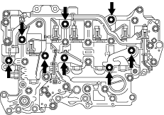
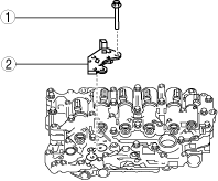
2.  Remove the ON/OFF solenoid using the following procedure:

azzjjw00000907

1
Bolt
2
ON/OFF solenoid

(1)  Remove the bolt shown in the figure.
azzjjw00000908
(2)  Remove the ON/OFF solenoid.
azzjjw00000909

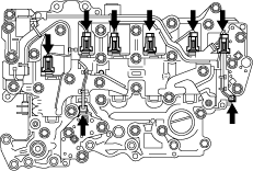
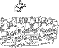
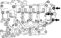
3.  Remove oil pressure switch B using the following procedure:

azzjjw00000910

1
3 bolts
2
Oil pressure switch B

(1)  Remove the bolts shown in the figure.
azzjjw00000911
(2)  Remove oil pressure switch B.
azzjjw00000912

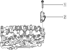
4.  Remove oil pressure switch A using the following procedure:

azzjjw00000913

1
3 bolts
2
Oil pressure switch A

(1)  Remove the bolts shown in the figure.
azzjjw00000914
(2)  Disengage oil pressure switch A tab.
azzjjw00000915
A  :Tab
(3)  Remove oil pressure switch A.
azzjjw00000916