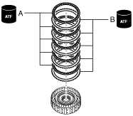
CLUTCH COMPONENT ASSEMBLY
id051700663700
Structural View
|
1
|
High clutch drum component
|
|
2
|
High clutch piston
|
|
3
|
Springs and retainer component (outer diameter approx. 87.5 mm {3.44 in})
|
|
4
|
Seal plate
|
|
5
|
Snap ring (outer diameter approx. 61.8 mm {2.43 in})
|
|
6
|
Driven plate (inner diameter approx. 106.8 mm {4.205 in})
|
|
7
|
Drive plate (outer diameter approx. 134.6 mm {5.299 in})
|
|
8
|
Retaining plate (inner diameter approx. 106.8 mm {4.205 in})
|
|
9
|
Snap ring (outer diameter approx. 144.6 mm {5.693 in}) (selection)
|
|
10
|
Wave spring
|
|
11
|
Driven plate (inner diameter approx. 160.0 mm {6.299 in})
|
|
12
|
Drive plate (outer diameter approx. 179.1 mm {7.051 in})
|
|
13
|
Retaining plate (inner diameter approx. 160.0 mm {6.299 in})
|
|
14
|
Snap ring (outer diameter approx. 189.3 mm {7.453 in}) (selection)
|
Assembly Procedure
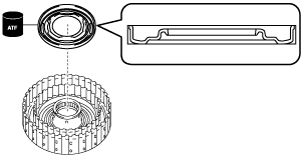
1. Assemble the high clutch piston using the following procedure:
- (1) Apply ATF (ATF FZ) to the high clutch piston lip.
- (2) Assemble the high clutch piston.
-
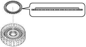
2. Assemble the springs and retainer component.
-
Note
-
• Springs and retainer component size: Outer diameter approx. 87.5 mm {3.44 in}
3. Assemble the seal plate using the following procedure:
- (1) Apply ATF (ATF FZ) to the seal plate lip.
- (2) Assemble the seal plate.
-
4. Assemble the snap ring using the following procedure:
-
Note
-
• Snap ring size: Outer diameter approx. 61.8 mm {2.43 in}
- (1) Set the snap ring to the top of the seal plate.
-
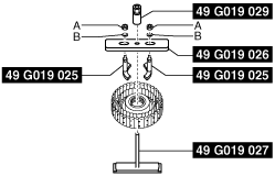
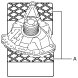
- (2) Install the SSTs.
-
-
Note
-
• When installing the SST (49 G019 025) to the SST (49 G019 026), use the nuts included with the SST (49 G019 025), or M8×1.25 nuts.
A :Nut included with SST (49 G019 025), or M8×1.25 nut
B :Washer
A :Nut included with SST (49 G019 025), or M8×1.25 nut
B :Washer
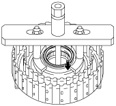
- (3) Tighten the SST (49 G019 029) until the snap ring groove of the high clutch drum component comes out.
-
-
Caution
-
• If the SST (49 G019 029) is tightened with excessive force, surrounding parts could be damaged. Stop tightening the SST when the snap ring groove of the high clutch drum component comes out.
A :Snap ring groove
- (4) Assemble the snap ring.
-
-
Caution
-
• After assembling the snap ring, verify that the snap ring is securely inserted into the bottom of the snap ring groove.
A :Snap ring
- (5) Loosen the SST (49 G019 029) and remove the SSTs.
-
A :Nut included with SST (49 G019 025), or M8×1.25 nut
B :Washer
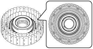
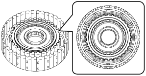
5. Assemble the drive plates and driven plates using the following procedure:
-
Note
-
• Drive plate size: Outer diameter approx. 134.6 mm {5.299 in}
• Driven plate size: Inner diameter approx. 106.8 mm {4.205 in}
- (1) Apply ATF (ATF FZ) to the drive plates and driven plates.
-
-
Caution
-
• If the drive plate is replaced with a new one, immerse it in ATF (ATF FZ) for 2 hours or more to permeate the facing with ATF.
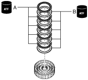
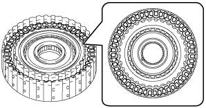
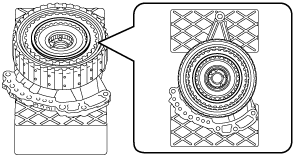
- (2) Assemble the drive plates and driven plates.
-
-
Assembly order
-
Driven plate—drive plate—driven plate—drive plate—driven plate—drive plate—driven plate—drive plate—driven plate—drive plate
A :Drive plate
B :Driven plate
6. Assemble the retaining plate.
-
Note
-
• Retaining plate size: Inner diameter approx. 106.8 mm {4.205 in}
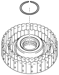
7. Assemble the snap ring using the following procedure:
-
Note
-
• Snap ring size: Outer diameter approx. 144.6 mm {5.693 in}
- (1) Measure the high clutch clearance and select the appropriate snap ring. (See HIGH CLUTCH CLEARANCE MEASUREMENT/ADJUSTMENT.)
-
-
Note
-
• If the snap ring is assembled for the high clutch clearance measurement/adjustment, the following snap ring assembly procedure is not necessary.
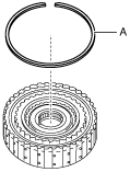
- (2) Assemble the selected snap ring in Step (1).
-
-
Caution
-
• After assembling the snap ring, verify that the snap ring is securely inserted into the bottom of the snap ring groove.
A :Snap ring (selection)
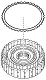
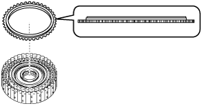
8. Assemble the wave spring.
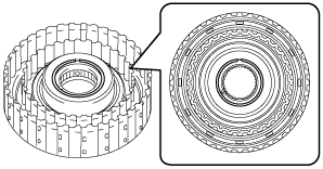
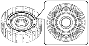
9. Assemble the drive plates and driven plates using the following procedure:
-
Note
-
• Drive plate size: Outer diameter approx. 179.1 mm {7.051 in}
• Driven plate size: Inner diameter approx. 160.0 mm {6.299 in}
- (1) Apply ATF (ATF FZ) to the drive plates and driven plates.
-
-
Caution
-
• If the drive plate is replaced with a new one, immerse it in ATF (ATF FZ) for 2 hours or more to permeate the facing with ATF.
- (2) Assemble the drive plates and driven plates.
-
-
Assembly order
-
Driven plate—drive plate—driven plate—drive plate—driven plate—drive plate—driven plate—drive plate—driven plate—drive plate
A :Drive plate
B :Driven plate
10. Assemble the retaining plate.
-
Note
-
• Retaining plate size: Inner diameter approx. 160.0 mm {6.299 in}
11. Assemble the snap ring using the following procedure:
-
Note
-
• Snap ring size: Outer diameter approx. 189.3 mm {7.453 in}
- (1) Measure the low clutch clearance and select the appropriate snap ring. (See LOW CLUTCH CLEARANCE MEASUREMENT/ADJUSTMENT.)
-
-
Note
-
• If the snap ring is assembled for the low clutch clearance measurement/adjustment, the following snap ring assembly procedure is not necessary.
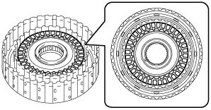
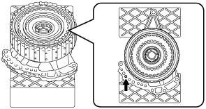
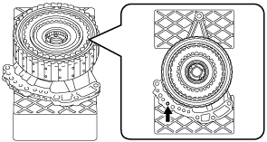
- (2) Assemble the selected snap ring in Step (1) to the position shown in the figure.
-
-
Caution
-
• Assemble so that the end gap of the snap ring is positioned diagonally opposed to the end gap of the snap ring for the high clutch.
• After assembling the snap ring, verify that the snap ring is securely inserted into the bottom of the snap ring groove.
A :Snap ring (selection)
A :Snap ring (low clutch)
B :Snap ring (high clutch)
12. Perform a operation verification of the low clutch and high clutch using the following procedure:
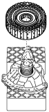
- (1) Set the oil pump on the workbench as shown in the figure.
-
-
Note
-
• Using the rubber plates, adjust the alignment surface of the oil pump with the transaxle case so that it is level.
A :Rubber plate
- (2) Assemble the thrust needle bearing to the clutch component using the following procedure:
-
-
Note
-
• Thrust needle bearing size: Outer diameter approx. 76.7 mm {3.02 in}
- 1) To prevent the thrust needle bearing from dropping out, apply ATF (ATF FZ) to the thrust needle bearing.
- 2) Assemble the thrust needle bearing.
-
- (3) Assemble the parts assembled together in Step (2) to the oil pump.
-
- (4) Blow compressed air into the oil passage shown in the figure and verify the operation condition of the low clutch.
-
-
Warning
-
• Always wear protective eye wear when using the air compressor. Otherwise, ATF or dirt particles blown off by the air compressor could get into the eyes.
-
Caution
-
• To prevent damage to parts, always use an air compressor which is adjusted to the indicated pressure.
-
Compressed air pressure
-
0.39—0.44 MPa {4.0—4.4 kgf/cm2, 57—63 psi}
-
• If there is a malfunction, perform disassembly again, verify the cause and repair the applicable part. (See
CLUTCH COMPONENT DISASSEMBLY.)
- (5) Blow compressed air into the oil passage shown in the figure and verify the operation condition of the high clutch.
-
-
Warning
-
• Always wear protective eye wear when using the air compressor. Otherwise, ATF or dirt particles blown off by the air compressor could get into the eyes.
-
Caution
-
• To prevent damage to parts, always use an air compressor which is adjusted to the indicated pressure.
-
Compressed air pressure
-
0.39—0.44 MPa {4.0—4.4 kgf/cm2, 57—63 psi}
-
• If there is a malfunction, perform disassembly again, verify the cause and repair the applicable part. (See
CLUTCH COMPONENT DISASSEMBLY.)
- (6) Remove the clutch component.
-
- (7) Remove the thrust needle bearing.
-
- (8) Take the oil pump off the rubber plates.
-