RING GEAR AND DIFFERENTIAL PRELOAD MEASUREMENT/ADJUSTMENT
id051700665100
Preparation Before Servicing
1. Print out the measurement/adjustment value input sheet. (See MEASUREMENT/ADJUSTMENT VALUE INPUT SHEET.)
-
Note
-
• When performing the measurement/adjustment, input the measured and calculated values into the measurement/adjustment value input sheet.
• If the measurement/adjustment value input sheet has already been printed out for the other measurements/adjustments, use the sheet.
Ring Gear and Differential Preload Measurement
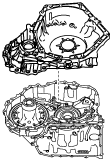
1. Rotate and adjust the rotation handle of the engine stand so that the converter housing side is facing upward.
2. Remove any remaining old sealant on the contact surfaces of the transaxle case and converter housing.
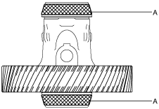
3. Assemble the ring gear and differential.
- (1) Apply ATF (ATF FZ) to the roller area of the tapered roller bearing of the ring gear and differential.
-
-
Caution
-
• Accurately perform the procedure to reduce the error on the ring gear and differential preload measurement.
A :ATF application area
- (2) Assemble the ring gear and differential.
-
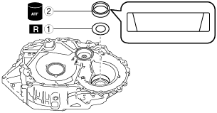
4. Assemble the bearing race and a new shim with the same thickness as the removed shim to the converter housing using the following procedure:
-
Caution
-
• Always use a new shim. If a deformed shim is reused, it may cause a transaxle malfunction.
- (1) Apply ATF (ATF FZ) to the engagement area of the bearing race and converter housing.
- (2) Assemble the bearing race and a new shim with the same thickness as the removed shim using the following procedure and the SSTs:
-
-
Caution
-
• After assembling the bearing race and a new shim, verify that the shim does not move. If the shim moves, press the bearing race again using the SSTs.
|
1
|
Shim (outer diameter approx. 89 mm {3.5 in})
(new shim with same thickness of removed shim)
|
|
2
|
Bearing race (outer diameter approx. 90 mm {3.5 in}, width approx. 21 mm {0.83 in})
|
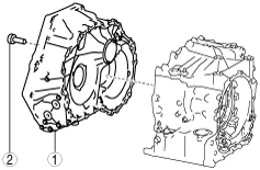
5. Assemble the converter housing using the following procedure:
|
1
|
Converter housing
|
|
2
|
25 bolts (M8×1.25 bolt, length approx. 28 mm {1.1 in})
|
- (1) Assemble the converter housing.
-
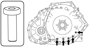
- (2) Assemble and temporarily tighten the bolts to the positions shown in the figure.
-
-
Note
-
• Bolt size: M8×1.25 bolt, length approx. 28 mm {1.1 in}
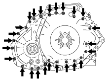
- (3) Assemble and temporarily tighten the bolts to the positions shown in the figure.
-
-
Caution
-
• When performing the automatic transaxle assembly after the ring gear and differential preload measurement/adjustment, use new bolts, otherwise ATF leakage could occur.
-
Note
-
• The bolts for the assembly are coated with sealant. However, the bolts are reused for removal after the ring gear and differential preload measurement/adjustment.
• Bolt size: M8×1.25 bolt, length approx. 28 mm {1.1 in}
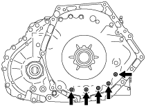
- (4) Tighten the bolts shown in the figure.
-
-
Tightening torque
-
19—25 N·m {2.0—2.5 kgf·m, 15—18 ft·lbf}
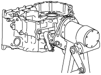
6. Measure the ring gear and differential preload using the following procedure.
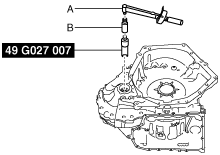
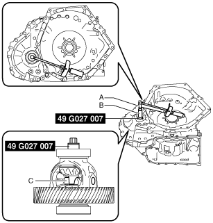
- (1) Set the SST, torque wrench, and socket (14 mm {9/16 in}) as shown in the figure.
-
-
Note
-
• Engage the groove on the end of the SST with the pinion shaft.
A :Torque wrench
B :Socket (14 mm {9/16 in})
A :Torque wrench
B :Socket (14 mm {9/16 in})
C :Pinion shaft
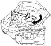
- (2) Rotate the ring gear and differential in the direction of the arrow shown in the figure using a torque wrench and measure the ring gear and differential preload.
-
-
Caution
-
• Measure the ring gear and differential preload after rotating the ring gear and differential approx. 10 times in the direction of the arrow shown in the figure to engage the tapered roller bearing.
• As a ring gear and differential preload, measure the rotational torque when the ring gear and differential is rotated at approx. 20 rpm (speed of one rotation for 3 s).
- (3) Input the measured ring gear and differential preload into the measurement/adjustment value input sheet.
- (4) Verify that the ring gear and differential preload satisfies the specification.
-
-
Specification
-
2.6—4.0 N·m {26.6—40.7 kgf·cm, 23.1—35.4 in·lbf}
-
- (5) Remove the SST, torque wrench, and socket (14 mm {9/16 in}).
-
A :Torque wrench
B :Socket (14 mm {9/16 in})
7. Remove the converter housing using the following procedure:
|
1
|
25 bolts
|
|
2
|
Converter housing
|
- (1) Remove the bolts shown in the figure.
-
-
Caution
-
• Sealant has been applied to the removed bolts. If the bolts are reused it could cause ATF leakage, therefore when performing the automatic transaxle assembly, use new bolts.
- (2) Remove the bolts shown in the figure.
-
- (3) Remove the converter housing.
-
8. Remove the ring gear and differential.
Ring Gear and Differential Preload Adjustment
1. Remove the SST, torque wrench, and socket (14 mm {9/16 in}).
A :Torque wrench
B :Socket (14 mm {9/16 in})
2. Remove the converter housing using the following procedure:
|
1
|
25 bolts
|
|
2
|
Converter housing
|
- (1) Remove the bolts shown in the figure.
-
-
Caution
-
• Sealant has been applied to the removed bolts. If the bolts are reused it could cause ATF leakage, therefore when performing the automatic transaxle assembly, use new bolts.
- (2) Remove the bolts shown in the figure.
-
- (3) Remove the converter housing.
-
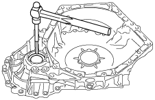
3. Remove the bearing race and shim using a pin punch and the procedure shown in the figure.
-
Caution
-
• Because the shim will deform when removing the bearing race, use a new shim when performing the shim assembly.
• Be careful not damage or scratch the converter housing when using a pin punch.
-
Note
-
• Lightly tap around the shim using a pin punch and remove the bearing race with the shim.
• Use a pin punch with an outer diameter on the end of approx.10 mm {0.39 in}. If the end of the pin punch is too thin it will put a hole in the shim and make it difficult to remove the bearing race.
4. Measure the thickness of the removed shim.
-
Note
-
• Recommended measuring instrument: Micrometer
5. Input the measured shim thickness into the measurement/adjustment value input sheet.
6. Perform the following calculation to calculate the preload gap.
-
Note
-
• The preload gap is the difference between the ring gear and differential preload and the median value of the ring gear and differential preload specification.
-
Preload gap = E - A
-
A: Ring gear and differential preload
E: Median value of ring gear and differential preload specification (3.3 N·m {33.7 kgf·cm, 29.2 in·lbf})
-
Note
-
Example
A: Ring gear and differential preload is 2.4 N·m {24.5 kgf·cm, 21.2 in·lbf}
Preload gap = 3.3 N·m {33.7 kgf·cm, 29.2 in·lbf} - 2.4 N·m {24.5 kgf·cm, 21.2 in·lbf}= 0.9 N·m {9.2 kgf·cm, 8.0 in·lbf}
7. Input the calculated preload gap into the measurement/adjustment value input sheet.
8. Perform the following calculation to calculate the shim thickness gap.
-
Note
-
• The shim thickness gap is the difference between the removed shim thickness and the optimum shim thickness.
• If the shim thickness is thickened 0.1 mm {0.00394 in}, the ring gear and differential preload increases approx. 1.6 N·m {16.3 kgf·cm, 14.1 in·lbf}.
-
Shim thickness gap = F × 0.1 mm {0.00394 in}/ 1.6 N·m {16.3 kgf·cm, 14.1 in·lbf}
-
F: Preload gap
-
Note
-
Example
F: Preload gap is 0.9 N·m {9.2 kgf·cm, 8.0 in·lbf}
Shim thickness gap = 0.9 N·m {9.2 kgf·cm, 8.0 in·lbf}× 0.1 mm {0.00394 in}/ 1.6 N·m {16.3 kgf·cm, 14.1 in·lbf}= 0.056 mm {0.00220 in}
9. Input the calculated shim thickness gap into the measurement/adjustment value input sheet.
10. Perform the following calculation to calculate the optimum shim thickness.
-
Optimum shim thickness = D + G
-
D: Thickness of removed shim
G: Shim thickness gap
-
Note
-
Example
D: Thickness of removed shim is 0.905 mm {0.03563 in}
G: Shim thickness gap is 0.056 mm {0.00220 in}
Thickness of optimum shim = 0.905 mm {0.03563 in}+ 0.056 mm {0.00220 in}= 0.961 mm {0.03783 in}
11. Input the calculated optimum shim thickness into the measurement/adjustment value input sheet.
12. Select a new shim of the nearest calculated optimum thickness from the following table:
|
Selected shim thickness
|
|
1.55 mm {0.0610 in}
|
|
1.50 mm {0.0591 in}
|
|
1.45 mm {0.0571 in}
|
|
1.40 mm {0.0551 in}
|
|
1.35 mm {0.0531 in}
|
|
1.30 mm {0.0512 in}
|
|
1.25 mm {0.0492 in}
|
|
1.20 mm {0.0472 in}
|
|
1.15 mm {0.0453 in}
|
|
1.10 mm {0.0433 in}
|
|
1.05 mm {0.0413 in}
|
|
1.00 mm {0.0394 in}
|
|
0.95 mm {0.0374 in}
|
|
0.90 mm {0.0354 in}
|
|
0.85 mm {0.0335 in}
|
|
0.80 mm {0.0315 in}
|
|
0.75 mm {0.0295 in}
|
|
0.70 mm {0.0276 in}
|
|
0.65 mm {0.0256 in}
|
|
0.60 mm {0.0236 in}
|
|
0.55 mm {0.0217 in}
|
13. Assemble the bearing race and selected new shim to the converter housing using the following procedure:
-
Caution
-
• Always use a new shim. If a deformed shim is reused, it may cause a transaxle malfunction.
- (1) Apply ATF (ATF FZ) to the engagement area of the bearing race and converter housing.
- (2) Assemble the bearing race and selected new shim using the following procedure and SSTs:
-
-
Caution
-
• After assembling the bearing race and a new shim, verify that the shim does not move. If the shim moves, press the bearing race again using the SSTs.
|
1
|
Shim (outer diameter approx. 89 mm {3.5 in})
(selected new shim)
|
|
2
|
Bearing race (outer diameter approx. 90 mm {3.5 in}, width approx. 21 mm {0.83 in})
|
14. Perform ring gear and differential preload measurement from Step 5. (See Ring Gear and Differential Preload Measurement.)