am6zzw00011809
|
DTC P0133:00 [SKYACTIV-G 2.0, SKYACTIV-G 2.5]
id0102h4702400
Details On DTCs
|
DESCRIPTION |
A/F sensor circuit slow response |
|
|---|---|---|
|
DETECTION CONDITION
|
Determination conditions
|
• The response speed of the A/F sensor input signal when the air/fuel ratio is fluctuated is slow.
|
|
Preconditions
|
• Engine speed: Within specified range
• Charging efficiency: Within specified range
• Engine coolant temperature: Specified value or more
• Mass airflow: Within specified range
• The following DTCs are not detected
|
|
|
Drive cycle
|
• 2
|
|
|
Self test type
|
• CMDTC self test
|
|
|
Sensor used
|
• A/F sensor
|
|
|
FAIL-SAFE FUNCTION
|
• Not applicable.
|
|
|
VEHICLE STATUS WHEN DTCs ARE OUTPUT
|
• Illuminates the check engine light
|
|
|
POSSIBLE CAUSE
|
• A/F sensor signal malfunction
• A/F sensor deterioration
• PCM malfunction
|
|
System Wiring Diagram
Function Explanation (DTC Detection Outline)
am6zzw00011809
|
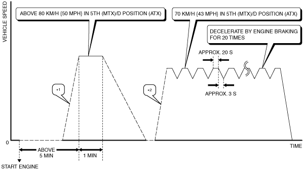
Repeatability Verification Procedure
am6zzw00011810
|
PID Item/Simulation Item Used In Diagnosis
PID/DATA monitor item table
|
Item |
Definition |
Unit |
Condition/Specification |
|---|---|---|---|
|
O2S11
|
A/F sensor input signal
|
µA
|
• Idle (after warm up): Approx. -39 µA
• Deceleration fuel cut (accelerator pedal released from engine speed of 4,000 rpm or more): Approx. 3.84 mA
|
Function Inspection Using M-MDS
|
STEP |
INSPECTION |
RESULTS |
ACTION |
|---|---|---|---|
|
1
|
PURPOSE: VERIFY RELATED SERVICE INFORMATION AVAILABILITY
• Verify related Service Information availability.
• Is any related Service Information available?
|
Yes
|
Perform repair or diagnosis according to the available Service Information.
• If the vehicle is not repaired, go to the next step.
|
|
No
|
Go to the next step.
|
||
|
2
|
PURPOSE: IDENTIFY TRIGGER DTC FOR FREEZE FRAME DATA (MODE 2)
• Is the DTC P0133:00 on FREEZE FRAME DATA (Mode 2)?
|
Yes
|
Go to the next step.
|
|
No
|
Go to the troubleshooting procedure for DTC on FREEZE FRAME DATA (Mode 2).
|
||
|
3
|
PURPOSE: RECORD VEHICLE STATUS AT TIME OF DTC DETECTION TO UTILIZE WITH REPEATABILITY VERIFICATION
• Has the FREEZE FRAME DATA (Mode 2)/snapshot data been recorded?
|
Yes
|
Go to the next step.
|
|
No
|
Record the FREEZE FRAME DATA (Mode 2)/snapshot data on the repair order, then go to the next step.
|
||
|
4
|
PURPOSE: VERIFY IF DIAGNOSTIC RESULT IS AFFECTED BY DTC OCCURRING FROM A/F SENSOR UNIT
• Switch the ignition to off, then to ON (engine off or on).
• Perform the Pending Trouble Code Access Procedure and DTC Reading Procedure.
• Is the PENDING CODE/DTC P0131:00, P0132:00, P0134:00, P2237:00, P2243:00 or P2251:00 also present?
|
Yes
|
Go to the applicable DTC inspection.
|
|
No
|
Go to the next step.
|
||
|
5
|
PURPOSE: VERIFY DTC
• Retrieve the PCM DTCs using the M-MDS.
• Are any DTCs present?
|
Yes
|
Go to the applicable DTC inspection.
|
|
No
|
Go to the next step.
|
||
|
6
|
PURPOSE: VERIFY A/F SENSOR
• Start the engine and idle it.
• Access the O2S11 PID using the M-MDS.
• Is the O2S11 PID value normal?
|
Yes
|
Go to the next step.
|
|
No
|
Go to the troubleshooting procedure to perform the procedure from Step 1.
|
Troubleshooting Diagnostic Procedure
|
STEP |
INSPECTION |
RESULTS |
ACTION |
|---|---|---|---|
|
1
|
PURPOSE: INSPECT A/F SENSOR CONNECTOR CONDITION
• Switch the ignition to off.
• Disconnect the A/F sensor connector.
• Inspect for poor connection (such as damaged/pulled-out pins, corrosion).
• Is there any malfunction?
|
Yes
|
Repair or replace the connector and/or terminals, then go to Step 16.
|
|
No
|
Go to the next step.
|
||
|
2
|
PURPOSE: INSPECT INSTALLATION OF A/F SENSOR
• Inspect installation of A/F sensor.
• Is the A/F sensor installed securely?
|
Yes
|
Go to the next step.
|
|
No
|
Retighten the A/F sensor, then go to Step 16.
|
||
|
3
|
PURPOSE: VERIFY IF MALFUNCTION RELATED TO EMISSION SYSTEM AFFECTS A/F SENSOR SIGNAL
• Verify the exhaust gas leakage from the exhaust system. (between A/F sensor and HO2S)
• Is there any malfunction?
|
Yes
|
Repair or replace the malfunctioning part according to the inspection results, then go to Step 16.
|
|
No
|
Go to the next step.
|
||
|
4
|
PURPOSE: DETERMINE INTEGRITY OF A/F SENSOR
• Reconnect all disconnected connectors.
• Inspect the A/F sensor.
• Is there any malfunction?
|
Yes
|
Replace the A/F sensor, then go to the next step.
|
|
No
|
Go to the next step.
|
||
|
5
|
PURPOSE: VERIFICATION OF VEHICLE REPAIR COMPLETION
• Make sure to reconnect all disconnected connectors.
• Clear the DTC from the PCM memory using the M-MDS.
• Implement the repeatability verification procedure.
• Perform the Pending Trouble Code Access Procedure.
• Is the PENDING CODE for this DTC present?
|
Yes
|
Repeat the inspection from Step 1.
• If the malfunction recurs, replace the PCM.
Go to the next step.
|
|
No
|
Go to the next step.
|
||
|
6
|
PURPOSE: VERIFY IF THERE IS ANY OTHER MALFUNCTION
• Is any other DTC or pending code stored?
|
Yes
|
Go to the applicable DTC inspection.
|
|
No
|
DTC troubleshooting completed.
|