|
ac5wzw00006718
SHIFT CONTROL MODULE REMOVAL/INSTALLATION [D66M-R]
id0515mb160200
Removal
1. Shift the shift lever to the neutral position.
2. Remove the front under cover No.2. (See FRONT UNDER COVER No.2 REMOVAL/INSTALLATION.)
3. Remove the engine cover. (See ENGINE COVER REMOVAL/INSTALLATION [SKYACTIV-D 2.2].)
4. Disconnect the negative battery cable. (See NEGATIVE BATTERY CABLE DISCONNECTION/CONNECTION [SKYACTIV-D 2.2].)
5. Remove the air cleaner and air hose as a single unit. (See INTAKE-AIR SYSTEM REMOVAL/INSTALLATION [SKYACTIV-D 2.2].)
6. Remove the battery and battery tray. (See BATTERY REMOVAL/INSTALLATION [SKYACTIV-D 2.2].)
7. Set the turbocharger air outlet pipe component aside as a single unit as shown in the figure. (See INTAKE-AIR SYSTEM REMOVAL/INSTALLATION [SKYACTIV-D 2.2].)
ac5wzw00006718
|
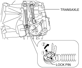
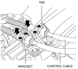
8. Disconnect the control cable from the transaxle.
ac5wzw00005919
|
ac5wzw00005920
|
9. Remove the neutral switch in the order shown in the figure
ac5wzw00005921
|
|
1
|
Connector
|
|
2
|
Neutral switch
|
|
3
|
Gasket
|
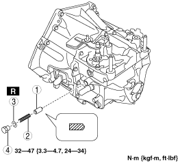
10. Remove the detent ball pin in the order shown in the figure
ac5wzw00005922
|
|
1
|
Plug
|
|
2
|
Gasket
|
|
3
|
Spring
|
|
4
|
Detent ball pin
|
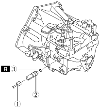
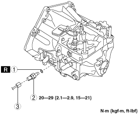
11. Remove the back-up light switch in the order shown in the figure
ac5wzw00005923
|
|
1
|
Connector
|
|
2
|
Back-up light switch
|
|
3
|
Gasket
|
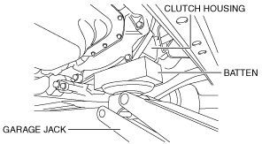
12. Support the transaxle using a garage jack.
ac5wzw00005924
|
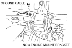
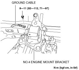
13. Remove the bolt shown in the figure and set the ground cable aside.
am6zzw00012266
|
14. Place alignment marks on the locations shown in the figure so that they can be assembled to the same positions as before removal.
ac5wzw00005926
|
15. Remove the No.4 engine mount bracket.
ac5wzw00005927
|
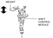
16. Remove the shift control module in the order shown in the figure
ac5wzw00005928
|
|
1
|
Breather
|
|
2
|
Shift control module
|
|
3
|
O-ring
|
Installation
1. Verify that the shift control module is in the neutral position.
ac5wzw00005929
|
2. Install the shift control module in the order shown in the figure
ac5wzw00005930
|
|
1
|
O-ring
|
|
2
|
Shift control module
|
|
3
|
Breather
|
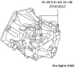
3. Tighten the stud bolts.
ac5wzw00005931
|
4. Install the No.4 engine mount bracket to No.4 engine mount rubber, and temporarily tighten the installation bolt.
ac5wzw00005932
|
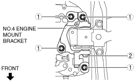
5. Align the alignment marks on the No.4 engine mount bracket and nuts, and temporarily tighten the nuts shown in the figure.
ac5wzw00005933
|
6. Tighten the No.4 engine mount bracket installation bolt and nuts in the order shown in the figure.
am6zzw00012267
|
|
No. |
Tightening torque |
|---|---|
|
1
|
92—116 N·m {9.4—11 kgf·m, 68—85 ft·lbf}
|
|
2
|
81—99 N·m {8.3—10 kgf·m, 60—73 ft·lbf}
|
7. Install the ground cable.
ac5wzw00005935
|
8. Install the back-up light switch in the order shown in the figure
ac5wzw00005936
|
|
1
|
Gasket
|
|
2
|
Back-up light switch
|
|
3
|
Connector
|
9. Install the detent ball pin in the order shown in the figure
ac5wzw00005937
|
|
1
|
Detent ball pin
|
|
2
|
Spring
|
|
3
|
Gasket
|
|
4
|
Plug
|
10. Install the neutral switch in the order shown in the figure
ac5wzw00005938
|
|
1
|
Gasket
|
|
2
|
Neutral switch
|
|
3
|
Connector
|
11. Connect the control cable to the transaxle.
ac5wzw00005939
|
12. Make sure that the shift lever can be shifted smoothly.
13. Install the turbocharger air outlet pipe, turbocharger air outlet hose, and air intake pipe aside as a single unit. (See INTAKE-AIR SYSTEM REMOVAL/INSTALLATION [SKYACTIV-D 2.2].)
14. Install the battery tray and battery. (See BATTERY REMOVAL/INSTALLATION [SKYACTIV-D 2.2].)
15. Install the air cleaner and air hose as a single unit. (See INTAKE-AIR SYSTEM REMOVAL/INSTALLATION [SKYACTIV-D 2.2].)
16. Connect the negative battery cable. (See NEGATIVE BATTERY CABLE DISCONNECTION/CONNECTION [SKYACTIV-D 2.2].)
17. Install the engine cover. (See ENGINE COVER REMOVAL/INSTALLATION [SKYACTIV-D 2.2].)
18. Install the front under cover No.2. (See FRONT UNDER COVER No.2 REMOVAL/INSTALLATION.)