ELECTRIC POWER STEERING (EPS) CONTROL MODULE


id061300245500


Purpose/ Function

•  The EPS control module (CM) calculates the optimum assist current based on the steering torque signal from the torque sensor installed to the steering column and the vehicle speed signal sent via CAN transmission from the PCM.
•  The following steering angle signals are output via CAN communication.
―  Steering angle (relative angle) signal
•  Set the steering position to 0 degrees when the ignition is switched ON (engine off or on) to output the steering angle when steering from that position.
―  Steering angle (estimated absolute angle) signal
•  The EPS CM performs the steering wheel angle neutral position determination using the steering wheel angle neutral position learning function based on the wheel speed signal, lateral-G signal, and yaw rate signal while driving.
•  Set the angle to 0 degrees during the steering wheel angle neutral position determination and the EPS CM calculates the steering angle, and outputs it.
•  The EPS CM controls the following functions:

Function Table

Control item

Function

EPS motor current control
•  Normal control
―  Calculates the proper assist current based on the steering torque, and the vehicle and engine speeds, and outputs a target current to the EPS motor.
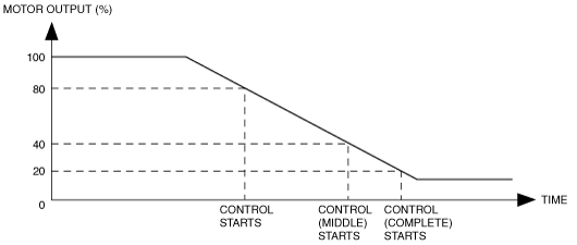
•  System overheating protection control
―  Monitors the temperature of the motherboard in the EPS CM and controls the motor current gradually to prevent overheating of the system.
•  Backup control
―  Even if a phase 1 open circuit malfunction in the EPS motor occurs, output current to the EPS motor is controlled so that steering assist is maintained.
•  EPS i-stop control
―  Control current to the EPS motor is increased or decreased according to the operation status of the i-stop system.
On-board diagnostic function
•  The main part of the system control includes the self-diagnosis function. In case a malfunction occurs, the power steering malfunction indicator light/master warning light illuminates to alert the driver, and a DTC is stored in the EPS CM at the same time.
•  As a result of the on-board diagnosis, when a malfunction is determined, system control is suspended or limited to assure safety while driving.
CAN communication function
•  Outputs the EPS status signal and power steering malfunction indicator light illuminates on request via CAN lines.
Automatic configuration function
•  When the ignition is switched to ON or the engine is started after the EPS CM have been replaced, the EPS CM reads data from the instrument cluster via CAN communication to perform automatic configuration.
Steering wheel angle neutral position automatic learning function
•  When the ignition is switched from OFF to ON (engine on) and the vehicle is driven normally, the steering wheel angle neutral position is learned automatically based on the wheel speed signal, lateral-G signal, and yaw rate signal.

Note
•  Before the steering wheel angle neutral position auto learning is completed, the EPS CM receives a steering angle (absolute angle) signal from the steering angle sensor via the start stop unit and outputs the signal to the other modules through the CAN communication (with adaptive front lighting system (AFS), Smart City Brake Support (SCBS), or park assist system).
•  The steering wheel angle neutral position is cleared when 1 min or more has elapsed after the ignition is switched off.
•  After the steering angle neutral position auto learning is completed, the EPS CM outputs an EPS status signal, which is calculated by EPS CM itself, through the CAN communication. (Without adaptive front lighting system (AFS), Smart City Brake Support (SCBS), and/or park assist system)

Block Diagram

am6zzn00002951

Construction

•  The EPS CM is installed to the steering column and integrated with the EPS motor.

Operation

•  The EPS CM (control module) calculates the optimum assist current based on the steering torque signal from the torque sensor installed to the steering column and the vehicle speed signal sent via CAN transmission from the PCM.
•  The EPS system control uses the steering angle (relative angle) signal.

EPS Motor Current Control

Normal control
•  The optimum assist current is calculated based on the steering force signal from the torque sensor and the vehicle and engine speeds signal from the PCM, and then the control current is output to the EPS motor.
System overheating protection control
•  The system overheating protection control lowers the current output to the EPS motor if the steering mechanism is turned from lock to lock continuously or the steering rack turning limit is reached repeatedly.
Note
•  During system overheating protection control, the assist force will feel weaker due to a decrease in the control current. This is normal for the EPS CM to prevent the EPS motor from burning or seizure, and it does not indicate a malfunction.
•  While the assist force weakens during this period of time, steering operation can be performed.
•  The system overheating protection control has middle and complete steps, and it can verify current conditions and the history using the PID/data monitor function and snap shot data.
―  System overheating protection control (middle): Motor output is 40 % or less (reference)
―  System overheating protection control (complete): Motor output is 20 % or less (reference)
•  The current output returns to normal if the temperature in the system decreases to the normal operation temperature.
ac5wzn00000268
Backup control
•  Even if an open circuit malfunction occurs in 1 out of the 3 phases in the EPS motor line, the backup control performs control to maintain steering assist.
•  If the EPS CM detects a phase 1 open circuit malfunction in the EPS motor, the EPS CM controls output current to the EPS motor using a calculation method different than during normal EPS CM control. As a result, even with a phase 1 open circuit malfunction, the steering assist can be maintained.
Note
•  If a phase 1 open circuit malfunction is detected in the EPS motor, the EPS CM stores DTC U2011:72 and illuminates the electric power steering malfunction indicator light/master warning light.
•  If the steering wheel is operated during backup control, the steering wheel operation may feel heavier (resistance) and vibrating.
EPS i-stop control
•  If it is detected that the engine is stopped by the i-stop control based on the i-stop condition signal from the PCM, the EPS motor control current is stopped.
•  If it is detected that the engine is restarted by the i-stop control, the EPS motor control current is increased and the system returns to normal control.
•  If the steering wheel is operated during EPS i-stop control, assist is performed (normal control) according to that steering.
•  If a malfunction is detected in the i-stop condition signal from the PCM, EPS i-stop control is not operated, and normal control is performed.
•  Depending on the vehicle condition, the EPS CM may continue assistance even after the engine is stopped.
•  Refer to i-stop for a detailed explanation of the i-stop. (See i-stop CONTROL [SKYACTIV-G 2.0, SKYACTIV-G 2.5].) (See i-stop CONTROL [SKYACTIV-D 2.2].)
ac5wzn00000269


Fail-safe

DTC No.

Fail-safe function

U2300:54
•  Control enabled
•  Power steering malfunction indicator light: Not illuminated
U2300:55
•  Control enabled
•  Power steering malfunction indicator light: Illuminated
U2300:56
•  Control enabled
•  Power steering malfunction indicator light: Not illuminated
U3000:16
•  Control disabled
•  Power steering malfunction indicator light: Illuminated
U3000:1C
U3000:28
U3000:41
U3000:44
U3000:46
•  Control is maintained in fail mode
•  Power steering malfunction indicator light: Not illuminated
U3000:47
•  Control disabled
•  Power steering malfunction indicator light: Illuminated
U3000:49
U3000:4B
•  Control is maintained in fail mode
•  Power steering malfunction indicator light: Not illuminated
U3000:61
•  Control disabled
•  Power steering malfunction indicator light: Illuminated
U3000:62
U3000:73
U3000:96
U3003:16
•  Control is maintained by gradually decreasing the motor control current
―  However, control is inhibited if the power supply voltage is the specified value of less
•  Power steering malfunction indicator light: Illuminated
U3003:17
•  Control disabled
•  Power steering malfunction indicator light: Illuminated