MANUAL AIR CONDITIONER CONTROL SYSTEM [MANUAL AIR CONDITIONER]
id0740a2101000
Outline
• The climate control unit performs the following controls based on the signals from each switch/dial and the sensor.
-
― Airflow temperature control
― Airflow volume control
― Airflow mode control
― Air intake control
― A/C compressor control
A/C cut-off control
-
Block Diagram
Outline of Control System
• The manual air conditioner system functions based on the five basic types of controls and three supplementary functions.
|
Control name
|
Control part
|
|
• Airflow temperature control
• Airflow volume control
• Airflow mode control
• Air intake control
• A/C compressor control
|
Climate control unit
|
|
Supplementary function
|
|
Fail-safe function
|
|
Sensor signal delay function
|
|
On-board diagnostic function
|
Sensor Signal Delay Function
• When the engine is restarted after being temporarily stopped, the ambient temperature sensor may detect a temperature higher than the actual ambient temperature.
• To prevent this, if the engine coolant temperature exceeds 55 °C {131 °F}, control of each system is performed based on the ambient temperature data before the engine was stopped, which is stored in the climate control unit.
Airflow Temperature Control
• The climate control unit drives the air mix actuator according to the operation of the temperature setting dial.
• The air mix actuator changed air mix door position.
Airflow Volume Control
• The climate control unit changes the blower motor applied voltage (airflow volume) in seven steps according to the operation of the airflow volume control dial.
|
Airflow volume control dial
|
Blower motor applied voltage
|
|
Except during i-stop control (engine stop )
|
During i-stop control (engine stop )
|
|
1st
|
3.7 V
|
3.7 V
|
|
2nd
|
5.2 V
|
3.7 V
|
|
3rd
|
6.9 V
|
3.7 V
|
|
4th
|
8.6 V
|
5.2 V
|
|
5th
|
10.0 V
|
6.9 V
|
|
6th
|
12.1 V
|
8.6 V
|
|
7th
|
14.6 V*1, 13.0V*2
|
10.0 V
|
*1 :When the airflow mode is except HEAT.
*2 :When the airflow mode is HEAT.
Start-up burn-out prevention function
-
• The start-up burn-out prevention function prevents the blower motor from being burnt out because of excess current.
• When the blower motor is started-up from the stopped status with a blower motor applied voltage of 4.4 V or more, the blower motor applied voltage is fixed at 4.4 V for 1 s.
Delay control
-
• When the blower motor rotation exceeds and rises above the blower motor applied voltage from a low speed condition, the delay control delays the blower motor applied voltage for approx. 1 s and stabilizes the motor operation.
Airflow Mode Control
• The climate control unit switches the airflow mode based on the MODE switch operation.
|
Airflow mode
|
Operation switch
|
Air vent
|
|
VENT
|
Mode switch
|
CENTER VENT, SIDE VENT
|
|
BI-LEVEL
|
CENTER VENT, SIDE VENT, FRONT HEAT, REAR HEAT
|
|
HEAT
|
FRONT HEAT, REAR HEAT, SIDE DEMISTER (low volume), DEFROSTER (low volume), SIDE VENT (low volume)
|
|
DEF/HEAT
|
FRONT HEAT, REAR HEAT, SIDE DEMISTER, DEFROSTER, SIDE VENT (low volume)
|
|
DEFROSTER
|
DEFROSTER switch
|
SIDE DEMISTER, DEFROSTER, SIDE VENT (low volume)
|
Air Intake Control
• The climate control unit switches the air intake mode based on the REC/FRESH switch operation.
|
Air intake mode
|
REC switch operation
|
|
FRESH
|
Fixed to FRESH when the FRESH switch is turned on during REC mode
|
|
REC
|
Fixed to REC when the RECIRCULATE switch is turned on during FRESH mode
|
Defroster control
-
• The defroster control improves the defrosting effect.
• When the defroster switch turns on, the climate control unit fixes the air intake mode to FRESH.
• The air intake is fixed at FRESH even if it has been set to REC manually.
REC mode control under severe heat
-
• When the vehicle is driven at a very low speed with the A/C on under a severe heat condition, the climate control unit may change the air intake mode from FRESH to REC automatically.
• Due to this, load to the A/C compressor is reduced.
• When the air intake mode is switched to REC, the indicator on the REC switch illuminates.
A/C Compressor Control
• The climate control unit sends the A/C signal to the PCM based on the signals sent from the A/C switch, airflow volume control dial, and evaporator temperature sensor.
• The PCM turns the A/C relay on/off based on the input signals from the A/C signal and A/C pressure sensor and controls the A/C compressor (magnetic clutch) operation.
A/C signal on/off control
-
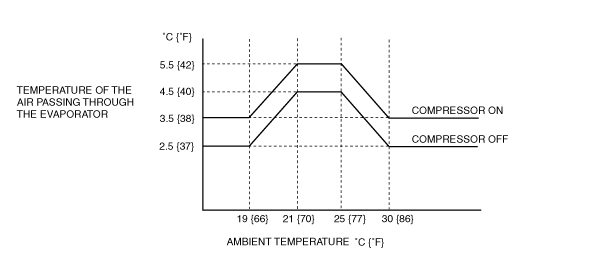
• When the A/C switch and fan switch are turned on, the climate control unit turns the A/C signal (magnetic clutch) on/off based on the temperature of the air passing through the evaporator.
• When the fan switch and A/C switch are turned on, the climate control unit controls the surface temperature of the evaporator so that it is within a certain range to prevent the evaporator from freezing.
• When the ambient temperature is low, the climate control unit sets the A/C signal (magnetic clutch) off-temperature to low to prevent window fogging.