 |
am6xuw00006602
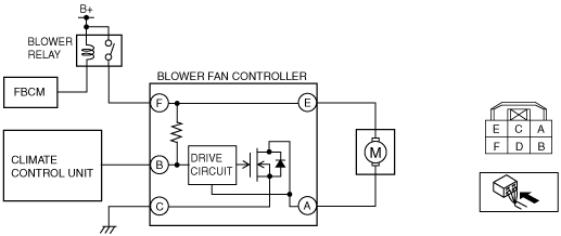
BLOWER FAN CONTROLLER INSPECTION [MANUAL AIR CONDITIONER]
id0740a2820100
1. Switch the ignition ON (engine off or on).
2. Connect the negative (-) lead of the tester to body ground.
3. By inserting the positive (+) lead of the tester into each blower fan controller terminal.
4. Measure the voltage according to the terminal voltage table.
am6xuw00006602
|
Terminal Voltage Table (Reference)
|
Terminal |
Signal name |
Connected to |
Measurement condition |
Voltage (V) |
Inspection item (s) |
|---|---|---|---|---|---|
|
A
|
Motor operation (-)
|
Blower motor
|
Switch the ignition off
|
1.0 or less
|
• Blower motor
• Related wiring harness
|
|
Fan stopped (Switch the ignition ON (engine off or on))
|
B+
|
||||
|
Fan: manual 1st
|
9.2
|
||||
|
Fan: manual 3rd
|
7.7
|
||||
|
Fan: manual 7th
|
1.0 or less
|
||||
|
B
|
Blower fan speed control
|
Climate control unit
|
• Related wiring harness
• Climate control unit
|
||
|
C
|
GND
|
Body ground
|
Under any condition
|
1.0 or less
|
• Related wiring harness
|
|
D
|
—
|
—
|
—
|
—
|
—
|
|
E
|
Motor operation (+)
|
Blower motor
|
Switch the ignition off
|
1.0 or less
|
• Blower motor
• Related wiring harness
|
|
Switch the ignition ON (engine off or on)
|
B+
|
||||
|
F
|
B+
|
Blower relay
|
Switch the ignition off
|
1.0 or less
|
• Related wiring harness
• Blower relay
|
|
Switch the ignition ON (engine off or on)
|
B+
|
||||
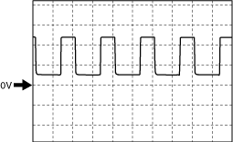
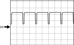
Blower Fan Speed Control Signal
Fan stopped
aatjjw00013135
|
Manual 1st
aatjjw00013136
|
Manual 3rd
am6zzw00015334
|
Manual 7th
aatjjw00013138
|