|
1
|
BATTERY INSPECTION
• Refer to the battery inspection and inspect the battery.
• Is the battery normal?
|
Yes
|
Go to the next step.
|
|
No
|
Replace or charge the battery.
Then go to Step 5.
|
|
2
|
FUSE INSPECTION
• Switch the ignition to off.
• Remove the SRS1 7.5 A fuse.
• Is the fuse normal?
|
Yes
|
Go to the next step.
|
|
No
|
Replace the SRS1 7.5 A fuse.
Then go to Step 5.
|
|
3
|
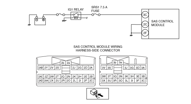
INSPECT WIRING HARNESS BETWEEN SAS CONTROL MODULE AND IG1 RELAY
-
Warning
-
• Handling the component parts improperly can accidentally operate (deploy) the air bag module, which may seriously injure you. Read the service warnings/cautions and the workshop manual before handling the air bag system components. (See AIR BAG SYSTEM SERVICE WARNINGS.)
• Install the SRS1 7.5 A fuse.
|
Yes
|
Go to the next step.
|
|
No
|
If there is a common connector:If there is no common connector:
Refer to the wiring diagram and verify whether or not there is a common connector between SAS control module terminal and IG1 relay terminal.
• Determine the malfunctioning part by inspecting the common connector and the terminal for corrosion, damage, or pin disconnection, and the common wiring harness for an open circuit or short to ground.
• Replace the malfunctioning part.
• Replace the wiring harness which has an open circuit or short to ground.
Go to Step 5.
|
|
3
|
INSPECT WIRING HARNESS BETWEEN SAS CONTROL MODULE AND IG1 RELAY
• Switch the ignition ON (engine off or on).
• Measure the voltage of SAS control module terminal 3C (wiring harness-side).
-
Note
-
• Measure the voltage while shaking the wiring harness between the SAS control module and IG1 relay.
• Is the voltage between 8–17.9 V?
|
|
|
|
4
|
INSPECT SAS CONTROL MODULE CIRCUIT FOR OPEN CIRCUIT
• SAS control module connectors are disconnected.
• Switch the ignition to off.
• Inspect the wiring harness between SAS control module connector terminal 2C, 2F (wiring harness-side) and body ground.
-
Note
-
• Inspect for continuity while shaking the wiring harness between the SAS control module and body ground.
• Is there continuity?
|
Yes
|
Go to the next step.
|
|
No
|
If there is a common connector:If there is no common connector:
Refer to the wiring diagram and verify whether or not there is a common connector between SAS control module terminal and body ground.
• Determine the malfunctioning part by inspecting the common connector and the terminal for corrosion, damage, or pin disconnection, and the common wiring harness for an open circuit.
• Replace the malfunctioning part.
• Replace the wiring harness which has an open circuit.
Go to the next step.
|
|
5
|
PERFORM SAS CONTROL MODULE DTC INSPECTION
• Connect the SAS control module connectors.
• Reconnect all disconnected connectors.
• Switch the ignition ON (engine off or on).
• Clear the DTC for the SAS control module using the M-MDS. (See CLEARING DTC.) • Perform the DTC inspection for the SAS control module using the M-MDS. (See DTC INSPECTION.) • Are the same DTCs present?
|
Yes
|
Replace the SAS control module. (See SAS CONTROL MODULE REMOVAL/INSTALLATION.) |
|
No
|
DTC troubleshooting completed.
|