ON-BOARD DIAGNOSIS SYSTEM [POSITION MEMORY SYSTEM]
id091300999500
Outline
• The on-board diagnostic function consists of the following functions: A malfunction detection function, which detects overall malfunctions in the position memory control module-related parts; a memory function, which stores detected DTCs; a display function, which indicates malfunction locations and status via DTC output; and a PID/data monitoring function, which reads out specific input/output signals and verifies the input/output condition.
• Using the Mazda Modular Diagnostic System (M-MDS), DTCs can be read out and deleted, and the PID/data monitoring function can be activated.
Malfunction detection function
• Detects malfunctions in input/output signals.
• If a malfunction occurs, the position memory control module records the malfunction as a DTC. A recorded DTC can be read by the Mazda Modular Diagnostic System (M-MDS).
DTC table
×: Applicable
—: Not applicable
|
DTC No.
|
Warning/indicator light
|
Description
|
Fail-safe function
|
Drive cycle
|
Self test type*1
|
Memory function
|
|
B1B87:13
|
—
|
Lift motor and position sensor circuit malfunction
|
×
|
—
|
C
|
×
|
|
B1B89:13
|
—
|
Slide motor and position sensor circuit malfunction
|
×
|
—
|
C
|
×
|
|
B1B91:13
|
—
|
Tilt motor and position sensor circuit malfunction
|
×
|
—
|
C
|
×
|
|
B1B93:13
|
—
|
Recliner motor and position sensor circuit malfunction
|
×
|
—
|
C
|
×
|
|
U0100:00
|
—
|
Communication error with PCM
|
×
|
—
|
C
|
×
|
|
U0101:00*2
|
—
|
Communication error with TCM
|
×
|
—
|
C
|
×
|
|
U0151:00
|
—
|
Communication error with SAS control module
|
×
|
—
|
C
|
×
|
|
U0155:00
|
—
|
Communication error with instrument cluster
|
×
|
—
|
C
|
×
|
|
U0214:00
|
—
|
Communication error with start stop unit
|
×
|
—
|
C
|
×
|
|
U3003:16
|
—
|
Position memory control module power supply voltage low input
|
—
|
—
|
C
|
×
|
*1 :C: CMDTC self test, D: ODDTC self test
*2 :ATX
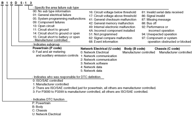
DTC 7-digit code definition
-
• When related systems or components have failed, the CM stores the DTC of the malfunctioning part in the CM memory, and allows for the retrieval of the store data using scanning tool when necessary. The DTCs are indicated using seven digits. Each digit indicates the following.
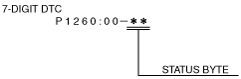
Status byte for DTC
-
• The status byte is the two digits (two digits after hyphen (-)) after the 7-digit DTC.
• The status byte is a code which indicates the pending code, current/past malfunction status, or warning illumination status.
• The status byte can be read by performing a CMDTC self-test using the Mazda Modular Diagnostic System (M-MDS).
• For details on the status byte, refer to the explanation on the Mazda Modular Diagnostic System (M-MDS) when reading the DTC.
Detection condition for the applicable DTC
|
DTC No.
|
System malfunction location
|
Detection condition
|
|
B1B87:13
|
Lift motor and position sensor circuit malfunction
|
• Position memory control module detects the following conditions during the lift motor operation control:
-
― Detects 4 times that current flowing to the lift motor is less than 1 A.
― Detects for 0.2 s that there is no change in the lift sensor pulse.
• Position memory control module detects any of the following conditions during the lift motor not operation control:
-
― Detects 4 times that current flowing to the lift motor exceeds 10 A.
― Detects 4 times that current flowing to the lift motor exceeds 1 A and a change in the lift sensor pulse 5 timeswithin 1 s.
• Position memory control module detects for 5 s that there is no change in the lift sensor pulse during the lift motor operation control.
|
|
B1B89:13
|
Slide motor and position sensor circuit malfunction
|
• Position memory control module detects the following conditions during the slide motor operation control:
-
― Detects 4 times that current flowing to the slide motor is less than 1 A.
― Detects for 0.2 s that there is no change in the slide sensor pulse.
• Position memory control module detects any of the following conditions during the slide motor not operation control:
-
― Detects 4 times that current flowing to the slide motor exceeds 10 A.
― Detects 4 times that current flowing to the slide motor exceeds 1 A and a change in the slide sensor pulse 5 timeswithin 1 s.
• Position memory control module detects for 5 s that there is no change in the slide sensor pulse during the slide motor operation control.
|
|
B1B91:13
|
Tilt motor and position sensor circuit malfunction
|
• Position memory control module detects the following conditions during the tilt motor operation control:
-
― Detects 4 times that current flowing to the tilt motor is less than 1 A.
― Detects for 0.2 s that there is no change in the tilt sensor pulse.
• Position memory control module detects any of the following conditions during the tilt motor not operation control:
-
― Detects 4 times that current flowing to the tilt motor exceeds 10 A.
― Detects 4 times that current flowing to the tilt motor exceeds 1 A and a change in the tilt sensor pulse 5 timeswithin 1 s.
• Position memory control module detects for 5 s that there is no change in the tilt sensor pulse during the tilt motor operation control.
|
|
B1B93:13
|
Recliner motor and position sensor circuit malfunction
|
• Position memory control module detects the following conditions during the recliner motor operation control:
-
― Detects 4 times that current flowing to the recliner motor is less than 1 A.
― Detects for 0.2 s that there is no change in the recliner sensor pulse.
• Position memory control module detects any of the following conditions during the recliner motor not operation control:
-
― Detects 4 times that current flowing to the recliner motor exceeds 10 A.
― Detects 4 times that current flowing to the recliner motor exceeds 1 A and a change in the recliner sensor pulse 5 timeswithin 1 s.
• Position memory control module detects for 5 s that there is no change in the recliner sensor pulse during the recliner motor operation control.
|
|
U0100:00
|
Communication error with PCM
|
Position memory control module could not receive the CAN signal from the PCM for 5 s or more.
|
|
U0101:00*1
|
Communication error with TCM
|
Position memory control module could not receive the CAN signal from the TCM for 5 s or more.
|
|
U0151:00
|
Communication error with SAS control module
|
Position memory control module could not receive the CAN signal from the SAS control module for 5 s or more.
|
|
U0155:00
|
Communication error with instrument cluster
|
Position memory control module could not receive the CAN signal from the instrument cluster for 5 s or more.
|
|
U0214:00
|
Communication error with start stop unit
|
Position memory control module could not receive the CAN signal from the start stop unit for 5 s or more.
|
|
U3003:16
|
Position memory control module power supply voltage low input
|
Position memory control module detects the following conditions:
• Position memory control module power supply circuit (terminal 1M) voltage of 9 V or less is detected.
• Position memory control module power supply circuit (terminal 1G) voltage of 6.5 V or more, 9V or less is detected for 10 s or more.
|
*1 :ATX
Data Monitor Function
• With the PID/data monitor function, input/output signal monitor items set in the position memory control module can be selected and read out in real-time.
PID/data monitor table
—: Not applicable
|
PID
|
Unit/Operation
|
Data contents
|
Inspection item(s)
|
|
FTLT_MTR_DN
|
Off/On
|
• Off: Tilt motor is not operated to down.
• On: Tilt motor is operated to down.
|
Tilt motor
|
|
FTLT_MTR_UP
|
Off/On
|
• Off: Tilt motor is not operated to up.
• On: Tilt motor is operated to up.
|
Tilt motor
|
|
FTLT_SW_DN
|
Off/On
|
• Off: Tilt switch is not in down.
• On: Tilt switch is in down.
|
Tilt switch
|
|
FTLT_SW_UP
|
Off/On
|
• Off: Tilt switch is not in up.
• On: Tilt switch is in up.
|
Tilt switch
|
|
M_SET_SW
|
Off/On
|
• Off: Position memory switch SET not pressed
• On: Position memory switch SET pressed
|
Position memory switch
|
|
MEMORY_SW_1
|
Off/On
|
• Off: Position memory switch 1 not pressed
• On: Position memory switch 1 pressed
|
Position memory switch
|
|
MEMORY_SW_2
|
Off/On
|
• Off: Position memory switch 2 not pressed
• On: Position memory switch 2 pressed
|
Position memory switch
|
|
REC_MTR_BK
|
Off/On
|
• Off: Recliner motor is not operated to back.
• On: Recliner motor is operated to back.
|
Recliner motor
|
|
REC_MTR_FW
|
Off/On
|
• Off: Recliner motor is not operated to front.
• On: Recliner motor is operated to front.
|
Recliner motor
|
|
REC_SW_DWN
|
Off/On
|
• Off: Recliner switch is not in down.
• On: Recliner switch is in down.
|
Recliner switch
|
|
REC_SW_UP
|
Off/On
|
• Off: Recliner switch is not in up.
• On: Recliner switch is in up.
|
Recliner switch
|
|
RTLT_MTR_DN
|
Off/On
|
• Off: Lift motor is not operated to down.
• On: Lift motor is operated to down.
|
Lift motor
|
|
RTLT_MTR_UP
|
Off/On
|
• Off: Lift motor is not operated to up.
• On: Lift motor is operated to up.
|
Lift motor
|
|
RTLT_SW_DN
|
Off/On
|
• Off: Lift switch is not in down.
• On: Lift switch is in down.
|
Lift switch
|
|
RTLT_SW_UP
|
Off/On
|
• Off: Lift switch is not in up.
• On: Lift switch is in up.
|
Lift switch
|
|
SLIDE_MTR_B
|
Off/On
|
• Off: Slide motor is not operated to back.
• On: Slide motor is operated to back.
|
Slide motor
|
|
SLIDE_MTR_F
|
Off/On
|
• Off: Slide motor is not operated to front.
• On: Slide motor is operated to front.
|
Slide motor
|
|
SLIDE_SW_B
|
Off/On
|
• Off: Slide switch is not in back.
• On: Slide switch is in back.
|
Slide switch
|
|
SLIDE_SW_F
|
Off/On
|
• Off: Slide switch is not in front.
• On: Slide switch is in front.
|
Slide switch
|
|
VPWR
|
V
|
Displays the position memory control module power supply voltage.
|
• Battery
• Position memory control module
|