Security indicator light flash pattern
(before displaying DTC)
DTC

09, 11, 13, 15, 16

22, 23
ON-BOARD DIAGNOSIS SYSTEM [IMMOBILIZER SYSTEM]
id0914001112c3
Outline
Function
On-board Diagnostic Function
|
Security indicator light flash pattern (before displaying DTC) |
DTC |
|---|---|
|
09, 11, 13, 15, 16
|
|
22, 23
|
DTC table
|
DTC |
KEY warning indicator light (red) |
Push button indicator light (amber) |
Description |
Fail-safe function |
Drive cycle |
Self test type*2 |
Memory function |
|||
|---|---|---|---|---|---|---|---|---|---|---|
|
M-MDS display*1 |
Security indicator light flash pattern |
|||||||||
|
Start stop unit |
PCM |
|||||||||
|
U3000:96
|
P1260:00
|
09
|
 |
On
|
Flash
|
Start stop unit malfunction
|
—
|
—
|
C
|
×
|
|
B10D9:87
|
P1260:00
|
11
|
 |
—
|
Flash
|
Coil antenna (built into push button start) error
|
—
|
—
|
C
|
—
|
|
B13D3:05
|
P1260:00
|
13
|
 |
—
|
—
|
Remote transmitter programming error
|
—
|
—
|
C
|
—
|
|
B13D3:94
|
P1260:00
|
13
|
—
|
—
|
Communication error with remote transmitter
|
—
|
—
|
C
|
—
|
|
|
B13D3:51
|
P1260:00
|
15
|
 |
—
|
Flash
|
Unregistered remote transmitter is detected
|
—
|
—
|
C
|
—
|
|
U0100:87
|
P1260:00
|
16
|
 |
—
|
—
|
Communication error with PCM (no response or data mis-matched)
|
—
|
—
|
C
|
—
|
|
B13D4:00
|
P1260:00
|
21
|
 |
On
|
—
|
Insufficient remote transmitter programming number
|
—
|
—
|
C
|
—
|
|
B10DA:51
|
P1260:00
|
22
|
 |
—
|
—
|
Communication error with PCM (data received failure)
|
—
|
—
|
C
|
—
|
|
B10DA:62
|
P1260:00
|
23
|
 |
—
|
—
|
Communication error with PCM (code mis-matched)
|
—
|
—
|
C
|
—
|
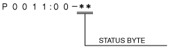
DTC 7-digit code definition
ac5uun00001110
|
Status byte for DTC
ac5wzn00002017
|
Detection condition for the applicable DTC
|
DTC |
System malfunction location |
Detection condition |
|---|---|---|
|
U3000:96/P1260:00
|
Start stop unit malfunction
|
Start stop unit malfunction detected.
|
|
B10D9:87/P1260:00
|
Coil antenna (built into push button start) error
|
Start stop unit detected a malfunction in the coil antenna, and remote transmitter communication is not possible
|
|
B13D3:05/P1260:00
|
Remote transmitter program error
|
Start stop unit detects a remote transmitter program error.
|
|
B13D3:94/P1260:00
|
Communication error with remote transmitter
|
Start stop unit could not detect the remote transmitter communication or communication error was detected.
|
|
B13D3:51/P1260:00
|
Unregistered remote transmitter is detected
|
Start stop unit detects that the remote transmitter has not been programmed.
|
|
U0100:87/P1260:00
|
Communication error with PCM (no response or data mis-match)
|
Start stop unit detects a communication error (no response or immobilizer system cancel not possible) with the PCM.
|
|
B13D4:00/P1260:00
|
Insufficient remote transmitter programming number
|
Start stop unit detects that the number of programmed remote transmitters is less than 2.
|
|
B10DA:51/P1260:00
|
Communication error with PCM (data received failure)
|
Start stop unit detects a communication error (data received failure) with PCM.
|
|
B10DA:62/P1260:00
|
Communication error with PCM (code mis-matched)
|
Start stop unit detects a communication error (code mis-matched) with the PCM..
|
PID/data Monitor Function
PID/data monitor table
|
PID |
Unit/Operation |
Data contents |
Inspection item(s) |
|---|---|---|---|
|
NUM_TRNSMIT
|
—
|
Displays the number of the remote transmitters programmed to the start stop unit.
|
Start stop unit
|