 |
am6zzw00010851
REAR OUTER HANDLE REMOVAL/INSTALLATION
id091400510200
1. To provide enough work space when removing the rear outer handle, open the rear door glass completely.
2. Disconnect the negative battery cable. (See NEGATIVE BATTERY CABLE DISCONNECTION/CONNECTION [SKYACTIV-D 2.2].) (See NEGATIVE BATTERY CABLE DISCONNECTION/CONNECTION [SKYACTIV-G 2.0, SKYACTIV-G 2.5].) (See NEGATIVE BATTERY CABLE DISCONNECTION/CONNECTION [SKYACTIV-G 2.0, SKYACTIV-G 2.5 (WITHOUT i-stop)].)
3. Remove the rear door trim. (See REAR DOOR TRIM REMOVAL/INSTALLATION.)
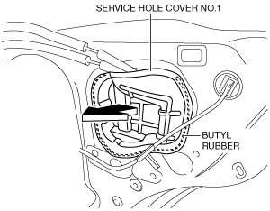
4. Remove service hole cover No. 1 in the direction of the arrow shown in the figure.
am6zzw00010851
|
5. Remove the service hole cover.
ac5wzw00001654
|
6. Loosen the screw from the rear outer handle bracket.
am6zzw00010852
|
7. While pressing the rear outer handle bracket tab in the direction of arrow (1) shown in the figure, pull the outer handle garnish in the direction of arrow (2) to detach the rear outer handle bracket from the outer handle garnish.
ac5wzw00001656
|
8. Remove the outer handle garnish from the rear outer handle bracket.
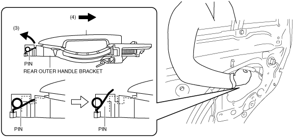
9. While pulling the rear outer handle bracket pin in the direction of arrow (3) shown in the figure, pull the rear outer handle in the direction of arrow (4) to detach the rear outer handle bracket pin from the rear outer handle.
ac5wzw00001657
|
10. Remove the rear outer handle in the direction of the arrow shown in the figure.
ac5wzw00001658
|
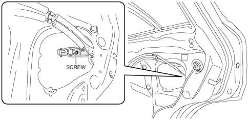
11. Loosen the screw from the rear outer handle bracket.
ac5wzw00001659
|
12. Pull the rear outer handle bracket in the direction of arrow (5) shown in the figure and detach the rear outer handle bracket hooks from the body.
ac5wzw00001660
|
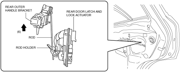
13. Lift the rear outer handle bracket in the direction of arrow (6) shown in the figure to pull the rod out of the rod holder. (See Rear Outer Handle Bracket Installation Note.)
ac5wzw00001661
|
14. Remove the rear outer handle bracket.
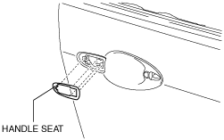
15. Remove the handle seat from the body.
ac5wzw00002741
|
16. Install in the reverse order of removal.
Rear Outer Handle Bracket Installation Note
ac5wzw00002755
|