 |
am6zzw00009615
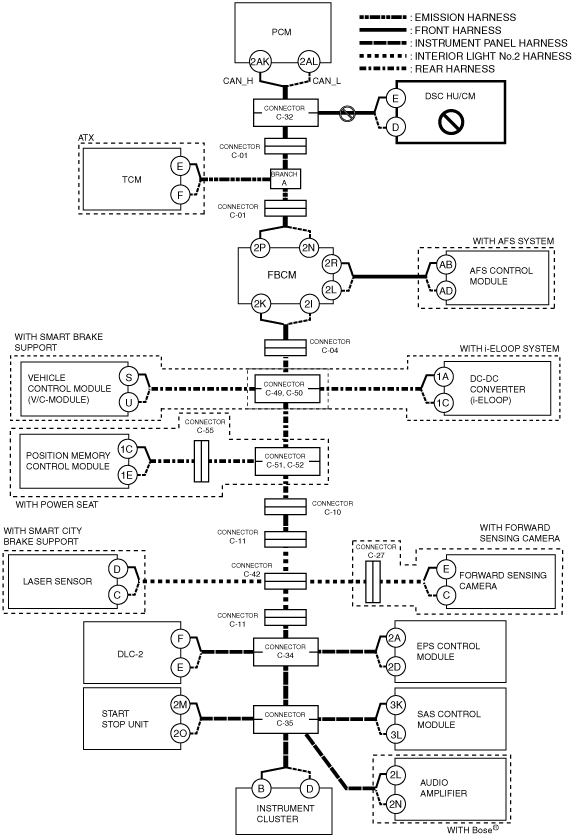
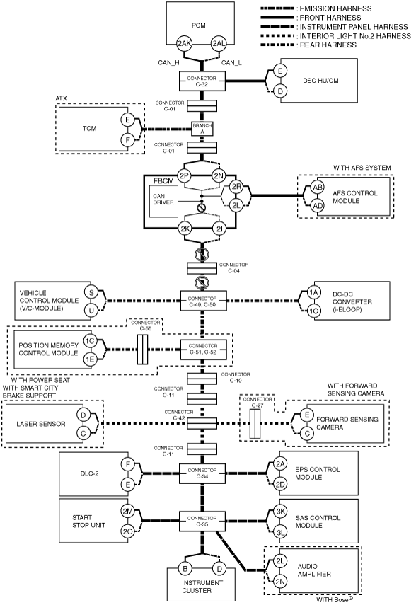
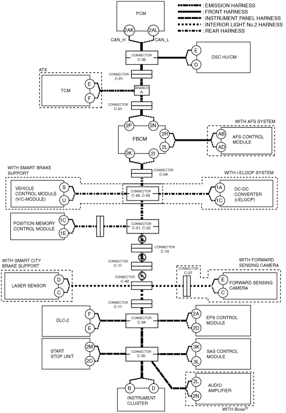
DETERMINING OPEN CIRCUIT LOCATION (HS-CAN) [SKYACTIV-G 2.0, SKYACTIV-G 2.5 (L.H.D.)]
id100208000400
1. Verify the CAN system-related module DTCs and the failed module on the M-MDS screen.
2. Apply the communication error DTC and the failed module to DTC output pattern and malfunctioning location, and select the possible cause for the diagnostic result and the reference for the inspection item.
3. Inspect the possible cause and inspection item of the applicable malfunctioning part.
4. After repairs, return to CONTROLLER AREA NETWORK (CAN) MALFUNCTION DIAGNOSIS FLOW [SKYACTIV-G 2.0, SKYACTIV-G 2.5 (L.H.D.)], and verify that the repairs have been completed.
DTC output pattern and malfunctioning location
|
M-MDS display |
DTC output pattern and malfunctioning location |
||||||||||||||||||||||
|---|---|---|---|---|---|---|---|---|---|---|---|---|---|---|---|---|---|---|---|---|---|---|---|
|
DTC output module |
DTC |
||||||||||||||||||||||
|
PCM
(PCM)
|
U0101:00
|
|
|
|
×
|
|
|
|
|
|
|
|
|
|
|
|
|||||||
|
U0104:00
|
|
|
|
|
|
|
|
|
×
|
|
|
|
|
|
|
|
|
||||||
|
U0121:00
|
|
×
|
|
|
|
|
|
|
|
|
|
|
|
|
|
|
|
||||||
|
U0131:00
|
|
|
|
|
|
|
|
|
|
|
|
|
|
|
|
|
×
|
||||||
|
U0140:00
|
|
|
|
|
|
|
×
|
|
|
|
|
|
|
|
|
|
|
||||||
|
U0151:00
|
|
|
|
|
|
|
|
|
|
|
|
|
|
|
|
|
|
×
|
×
|
||||
|
U0155:00
|
|
|
|
|
|
|
|
|
|
|
|
|
|
|
|
|
|
×
|
×
|
||||
|
U0214:00
|
|
|
|
|
|
|
|
|
|
|
|
|
|
|
|
|
|
×
|
×
|
||||
|
U0235:00
|
|
|
|
|
|
|
|
|
|
|
|
|
|
×
|
|
|
|
||||||
|
U0298:00
|
|
|
|
|
|
|
|
|
|
×
|
|
|
|
|
|
|
|
||||||
|
ABS
(DSC HU/CM)
|
U0100:00
|
×
|
|
|
|
|
|
|
|
|
|
|
|
|
|
|
|
|
|||||
|
U0101:00
|
|
|
|
×
|
|
|
|
|
|
|
|
|
|
|
|
|
|
||||||
|
U0104:00
|
|
|
|
|
|
|
|
|
×
|
|
|
|
|
|
|
|
|
||||||
|
U0131:00
|
|
|
|
|
|
|
|
|
|
|
|
|
|
|
|
|
×
|
||||||
|
U0154:00
|
|
|
|
|
|
|
|
|
|
|
|
|
|
|
|
|
|
×
|
×
|
||||
|
U0155:00
|
|
|
|
|
|
|
|
|
|
|
|
|
|
|
|
|
|
×
|
×
|
||||
|
U0214:00
|
|
|
|
|
|
|
|
|
|
|
|
|
|
|
|
|
|
×
|
×
|
||||
|
U0235:00
|
|
|
|
|
|
|
|
|
|
|
|
|
|
×
|
|
|
|
||||||
|
TCM*1
(TCM)
|
U0100:00
|
×
|
|
×
|
|
|
|
|
|
|
|
|
|
|
|
|
|
|
|||||
|
U0121:00
|
|
×
|
×
|
|
|
|
|
|
|
|
|
|
|
|
|
|
|
||||||
|
U0131:00
|
|
|
|
|
|
|
|
|
|
|
|
|
|
|
|
|
×
|
||||||
|
U0141:00
|
|
|
|
|
|
|
×
|
|
|
|
|
|
|
|
|
|
|
||||||
|
U0155:00
|
|
|
|
|
|
|
|
|
|
|
|
|
|
|
|
|
|
×
|
×
|
||||
|
F_BCM
(Front body control module (FBCM))
|
U0100:00
|
×
|
|
×
|
|
×
|
|
|
|
|
|
|
|
|
|
|
|
|
|||||
|
U0101:00
|
|
|
|
×
|
×
|
|
|
|
|
|
|
|
|
|
|
|
|
||||||
|
U0121:00
|
|
×
|
×
|
|
×
|
|
|
|
|
|
|
|
|
|
|
|
|
||||||
|
U0155:00
|
|
|
|
|
|
|
|
|
|
|
|
|
|
|
|
|
|
×
|
×
|
||||
|
U0214:00
|
|
|
|
|
|
|
|
|
|
|
|
|
|
|
|
|
|
×
|
×
|
||||
|
U023A:00
|
|
|
|
|
|
|
|
|
|
|
|
|
|
|
×
|
|
|
||||||
|
U0515:00
|
|
|
|
|
|
|
|
|
|
|
|
|
|
|
|
|
|
×
|
|||||
|
AFS*2
(AFS control module)
|
U0100:00
|
×
|
|
×
|
|
×
|
|
|
|
|
|
|
|
|
|
|
|
|
|||||
|
U0131:00
|
|
|
|
|
|
|
|
|
|
|
|
|
|
|
|
|
×
|
||||||
|
U0140:00
|
|
|
|
|
|
|
×
|
|
|
|
|
|
|
|
|
|
|
||||||
|
U0155:00
|
|
|
|
|
|
|
|
|
|
|
|
|
|
|
|
|
|
×
|
×
|
||||
|
SBS/MRCC*3
(vehicle control module (V/C-module))
|
U0100:00
|
×
|
|
×
|
|
×
|
|
|
×
|
|
|
|
|
|
|
|
|
|
|||||
|
U0101:00
|
|
|
|
×
|
×
|
|
|
×
|
|
|
|
|
|
|
|
|
|
||||||
|
U0121:00
|
|
×
|
×
|
|
×
|
|
|
×
|
|
|
|
|
|
|
|
|
|
||||||
|
U0140:00
|
|
|
|
|
|
×
|
×
|
|
|
|
|
|
|
|
|
|
|||||||
|
U0214:00
|
|
|
|
|
|
|
|
|
|
|
|
|
|
|
|
|
|
×
|
×
|
||||
|
U0151:00
|
|
|
|
|
|
|
|
|
|
|
|
|
|
|
|
|
|
×
|
×
|
||||
|
U0155:00
|
|
|
|
|
|
|
|
|
|
|
|
|
|
|
|
|
|
×
|
×
|
||||
|
U0131:00
|
|
|
|
|
|
|
|
|
|
|
|
|
|
|
|
|
×
|
||||||
|
U023A:00
|
|
|
|
|
|
|
|
|
|
|
|
|
|
|
×
|
|
|
||||||
|
U0285:68
|
|
|
|
|
|
|
|
|
|
|
|
|
|
×
|
|
|
|
||||||
|
DCDC*4
(DC-DC converter (i-ELOOP))
|
U0100:00
|
×
|
|
×
|
|
×
|
|
×
|
|
|
|
|
|
|
|
||||||||
|
U0155:00
|
|
|
|
|
|
|
|
|
|
|
|
|
|
|
|
|
|
×
|
×
|
||||
|
DSM*5
(Position memory control module)
|
U0100:00
|
×
|
|
×
|
|
×
|
|
|
×
|
|
|
×
|
|
|
|
|
|
|
|||||
|
U0101:00
|
|
|
|
×
|
×
|
|
|
×
|
|
|
×
|
|
|
|
|
|
|
||||||
|
U0151:00
|
|
|
|
|
|
|
|
|
|
|
|
|
|
|
|
|
|
×
|
×
|
||||
|
U0155:00
|
|
|
|
|
|
|
|
|
|
|
|
|
|
|
|
|
|
×
|
×
|
||||
|
U0214:00
|
|
|
|
|
|
|
|
|
|
|
|
|
|
|
|
|
|
×
|
×
|
||||
|
SCBS*6
(Laser sensor)
|
U0100:00
|
×
|
|
×
|
|
×
|
|
|
×
|
|
|
×
|
|
×
|
|
|
|
|
|||||
|
U0121:00
|
|
×
|
×
|
|
×
|
|
|
×
|
|
|
×
|
|
×
|
|
|
|
|
||||||
|
U0131:00
|
|
|
|
|
|
|
|
|
|
|
|
|
|
|
|
|
×
|
||||||
|
U0155:00
|
|
|
|
|
|
|
|
|
|
|
|
|
|
|
|
|
|
×
|
×
|
||||
|
FSC*7
(Forward sensing camera)
|
U0100:00
|
×
|
|
×
|
|
×
|
|
|
×
|
|
|
×
|
|
×
|
|
|
|
|
|||||
|
U0121:00
|
|
×
|
×
|
|
×
|
|
|
×
|
|
|
×
|
|
×
|
|
|
|
|
||||||
|
U0131:00
|
|
|
|
|
|
|
|
|
|
|
|
|
|
|
|
|
×
|
||||||
|
U0140:00
|
|
|
|
|
|
|
×
|
×
|
|
|
×
|
|
×
|
|
|
|
|
||||||
|
U0155:00
|
|
|
|
|
|
|
|
|
|
|
|
|
|
|
|
|
|
×
|
×
|
||||
|
U0214:00
|
|
|
|
|
|
|
|
|
|
|
|
|
|
|
|
|
|
×
|
×
|
||||
|
EPS
(control module (EPS)
|
U0100:00
|
×
|
|
×
|
|
×
|
|
|
×
|
|
|
×
|
|
×
|
|
|
×
|
|
|||||
|
U0121:00
|
|
×
|
×
|
|
×
|
|
|
×
|
|
|
×
|
|
×
|
|
|
×
|
|
||||||
|
U0155:00
|
|
|
|
|
|
|
|
|
|
|
|
|
|
|
|
|
|
×
|
×
|
||||
|
(SSU)
Start stop unit
|
U0100:00
|
×
|
|
×
|
|
×
|
|
|
×
|
|
|
×
|
|
×
|
|
|
×
|
|
|||||
|
U0101:00
|
|
|
|
×
|
×
|
|
|
×
|
|
|
×
|
|
×
|
|
|
×
|
|
||||||
|
U0121:00
|
|
×
|
×
|
|
×
|
|
|
×
|
|
|
×
|
|
×
|
|
|
×
|
|
||||||
|
U0121:87
|
|
×
|
×
|
|
×
|
|
|
×
|
|
|
×
|
|
×
|
|
|
×
|
|
||||||
|
U0131:00
|
|
|
|
|
|
|
|
|
|
|
|
|
|
|
|
|
×
|
||||||
|
U0140:00
|
|
|
|
|
|
|
×
|
×
|
|
|
×
|
|
×
|
|
|
×
|
|
||||||
|
U0146:00
|
|
|
|
|
|
|
|
|
|
|
|
|
|
|
|
|
|
||||||
|
U0151:00
|
|
|
|
|
|
|
|
|
|
|
|
|
|
|
|
|
|
×
|
|||||
|
U0155:00
|
|
|
|
|
|
|
|
|
|
|
|
|
|
|
|
|
|
×
|
|||||
|
RCM
(SAS control module)
|
U0155:00
|
|
|
|
|
|
|
|
|
|
|
|
|
|
|
|
|
|
×
|
||||
|
IC
(Instrument cluster)
|
U0100:00
|
×
|
|
×
|
|
×
|
|
|
×
|
|
|
×
|
|
×
|
|
|
×
|
|
|||||
|
U0101:00
|
|
|
|
×
|
×
|
|
|
×
|
|
|
×
|
|
×
|
|
|
×
|
|
||||||
|
U0104:00
|
|
|
|
|
|
|
|
|
×
|
|
×
|
|
×
|
|
|
×
|
|
||||||
|
U0121:00
|
|
×
|
×
|
|
×
|
|
|
×
|
|
|
×
|
|
×
|
|
|
×
|
|
||||||
|
U0131:00
|
|
|
|
|
|
|
|
|
|
|
|
|
|
|
|
|
×
|
||||||
|
U0140:00
|
|
|
|
|
|
|
×
|
×
|
|
|
×
|
|
×
|
|
|
×
|
|
||||||
|
U0151:00
|
|
|
|
|
|
|
|
|
|
|
|
|
|
|
|
|
|
×
|
|||||
|
U0182:00
|
|
|
|
|
|
×
|
|
×
|
|
|
×
|
|
×
|
|
|
×
|
|
||||||
|
U0214:00
|
|
|
|
|
|
|
|
|
|
|
|
|
|
|
|
|
|
×
|
|||||
|
U0235:00
|
|
|
|
|
|
|
|
|
|
|
|
|
|
×
|
|
×
|
|
||||||
|
U023A:00
|
|
|
|
|
|
|
|
|
|
|
|
|
|
|
×
|
×
|
|
||||||
|
M-MDS display module
|
[Fail] display pattern
|
||||||||||||||||||||||
|
PCM
|
×
|
|
×
|
|
×
|
|
|
×
|
|
|
×
|
|
×
|
|
|
×
|
|
||||||
|
ABS
|
|
×
|
×
|
|
×
|
|
|
×
|
|
|
×
|
|
×
|
|
|
×
|
|
||||||
|
TCM*1
|
|
|
|
×
|
×
|
|
|
×
|
|
|
×
|
|
×
|
|
|
×
|
|
||||||
|
F_BCM
|
|
|
|
|
|
|
×
|
×
|
|
|
×
|
|
×
|
|
|
×
|
|
||||||
|
AFS*2
|
|
|
|
|
|
×
|
|
×
|
|
|
×
|
|
×
|
|
|
×
|
|
||||||
|
SBS/MRCC*3
|
|
|
|
|
|
|
|
|
×
|
|
×
|
|
×
|
|
|
×
|
|
||||||
|
DCDC*4
|
|
|
|
|
|
|
|
|
|
×
|
×
|
|
×
|
|
|
×
|
|
||||||
|
DSM*5
|
|
|
|
|
|
|
|
|
|
|
|
×
|
×
|
|
|
×
|
|
||||||
|
SCBS*6
|
|
|
|
|
|
|
|
|
|
|
|
|
|
×
|
|
×
|
|
||||||
|
FSC*7
|
|
|
|
|
|
|
|
|
|
|
|
|
|
|
×
|
×
|
|
||||||
|
EPS
|
|
|
|
|
|
|
|
|
|
|
|
|
|
|
|
|
×
|
||||||
|
SSU
|
|
|
|
|
|
|
|
|
|
|
|
|
|
|
|
|
|
×
|
×
|
||||
|
RCM
|
|
|
|
|
|
|
|
|
|
|
|
|
|
|
|
|
|
×
|
×
|
||||
|
AM*8
|
|
|
|
|
|
|
|
|
|
|
|
|
|
|
|
|
|
×
|
×
|
||||
|
IC
|
|
|
|
|
|
|
|
|
|
|
|
|
|
|
|
|
|
×
|
×
|
||||
|
Diagnostic result
|
|||||||||||||||||||||||
|
Possible cause and inspection item
|
|||||||||||||||||||||||
A
Possible cause
System wiring diagram
am6zzw00009615
|
Inspection item
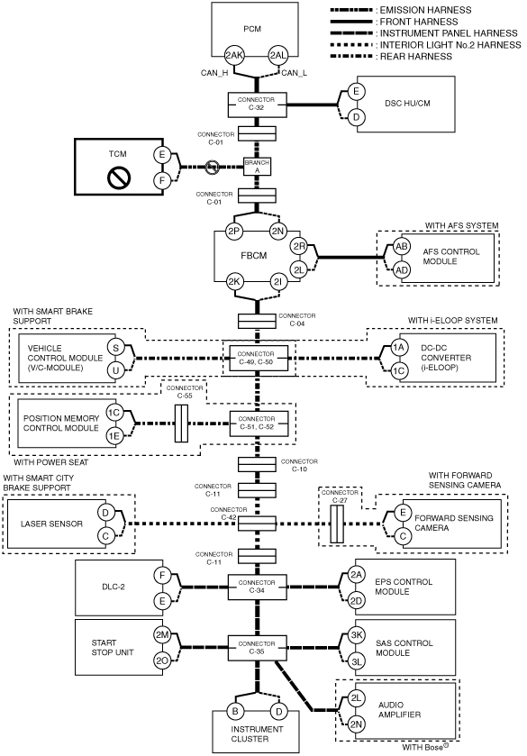
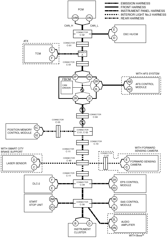
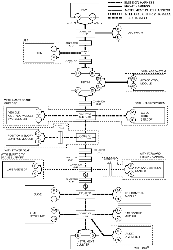
B
Possible cause
System wiring diagram
am6zzw00009616
|
Inspection item
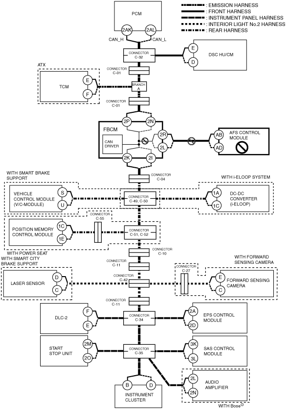
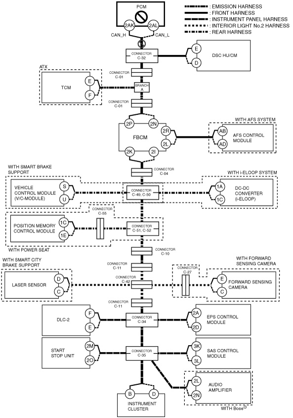
C
ATX vehicles
System wiring diagram
am6zzw00009617
|
MTX vehicles
System wiring diagram
am6zzw00009618
|
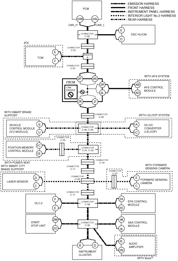
D
Possible cause
System wiring diagram
am6zzw00009619
|
Inspection item
E
Possible cause
System wiring diagram
am6zzw00009620
|
Inspection item
F
Possible cause
System wiring diagram
am6zzw00009621
|
Inspection item
G
Possible cause
System wiring diagram
am6zzw00009622
|
Inspection item
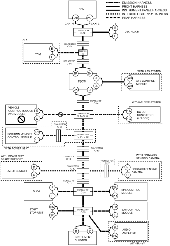
H
With smart brake support or i-ELOOP system
System wiring diagram
am6zzw00009623
|
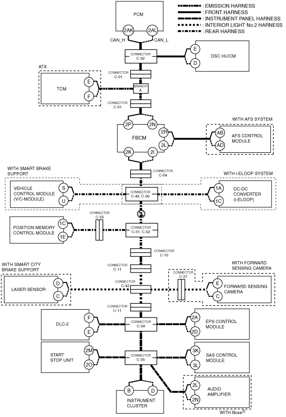
With smart brake support or i-ELOOP system
System wiring diagram
am6zzw00009624
|
I
Possible cause
System wiring diagram
am6zzw00009625
|
Inspection item
J
Possible cause
System wiring diagram
am6zzw00009626
|
Inspection item
K
Possible cause
System wiring diagram
am6zzw00009627
|
Inspection item
L
Possible cause
System wiring diagram
am6zzw00009628
|
Inspection item
M
Possible cause
System wiring diagram
am6zzw00009629
|
Inspection item
N
Possible cause
System wiring diagram
am6zzw00009630
|
Inspection item
O
Possible cause
System wiring diagram
am6zzw00009631
|
Inspection item
P
Possible cause
System wiring diagram
am6zzw00009632
|
Inspection item
Q
Possible cause
System wiring diagram
am6zzw00009633
|
Inspection item
R
Possible cause
System wiring diagram
am6zzw00009634
|
Inspection item
S
Possible cause
System wiring diagram
am6zzw00009635
|
Inspection item
T
Possible cause
System wiring diagram
am6zzw00009636
|
Inspection item
U
Possible cause
System wiring diagram
am6zzw00009637
|
Inspection item
V
Possible cause
System wiring diagram
am6zzw00009638
|
Inspection item