|
1
|
DETERMINE IF MALFUNCTION CAUSED BY A/C SYSTEM OPERATION
• Verify the A/C system operation.
• Is the A/C system operation normal?
|
Yes
|
Go to the next step.
|
|
No
|
Perform the symptom troubleshooting “NO.28 A/C DOES NOT WORK SUFFICIENTLY” and “NO.29 A/C IS ALWAYS ON OR A/C COMPRESSOR RUNS CONTINUOUSLY”.
|
|
2
|
DETERMINE IF MALFUNCTION CAUSED BY ATX BODY
• Compare the malfunction symptom with the i-stop system stop condition.
• Is there any shock or slippage during acceleration with the i-stop system disabled?
|
Yes
|
Perform the applicable symptom troubleshooting procedure.
|
|
No
|
Go to the next step.
|
|
3
|
VERIFY DTC
• Retrieve the PCM, TCM, DSC HU/CM, SAS control module DTCs using the M-MDS.
• Are any DTCs present?
|
Yes
|
Go to the applicable DTC inspection.
|
|
No
|
Go to the next step.
|
|
4
|
DETERMINE IF MALFUNCTION CAUSE IS BRAKE FLUID PRESSURE SENSOR SIGNAL OR OTHER
• Put the vehicle in an i-stop condition (engine stopped).
• Monitor the PCM PID BFP using the M-MDS while the brake is depressed and held with the i-stop function operating.
• Does the monitoring value change?
|
Yes
|
Brake fluid pressure sensor (built-into DSC HU/CM) or DSC HU/CM brake pressure hold function malfunction.
|
|
No
|
Go to the next step.
|
|
5
|
INSPECT ELECTRIC AT OIL PUMP CONNECTOR CONDITION
• Switch the ignition to off.
• Disconnect the electric AT oil pump connector.
• Inspect for poor connection (such as damaged/pulled-out pins, corrosion).
• Is there any malfunction?
|
Yes
|
Repair or replace the connector and/or terminals.
|
|
No
|
Go to the next step.
|
|
6
|
DETERMINE IF MALFUNCTION CAUSE ELECTRIC AT OIL PUMP POWER SUPPLY CIRCUIT OR OTHER
• Verify that the electric AT oil pump connector is disconnected.
• Measure the voltage at the electric AT oil pump terminal D (wiring harness-side) while the engine stop with i-stop function operating.
• Is the voltage B+?
|
Yes
|
Go to Step 14.
|
|
No
|
Go to the next step.
|
|
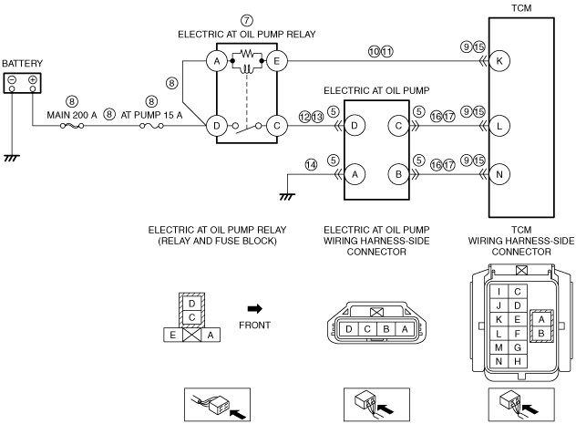
7
|
INSPECT ELECTRIC AT OIL PUMP RELAY
• Switch the ignition to off.
• Remove the electric AT oil pump relay.
• Inspect the electric AT oil pump relay.
• Is there any malfunction?
|
Yes
|
Replace the electric AT oil pump relay.
|
|
No
|
Go to the next step.
|
|
8
|
INSPECT ELECTRIC AT OIL PUMP RELAY POWER SUPPLY CIRCUIT FOR SHORT TO GROUND OR OPEN CIRCUIT
• Verify that the electric AT oil pump relay is removed.
• Verify that the electric AT oil pump connector is disconnected.
• Measure the voltage at the following terminals (wiring harness-side):
-
― Electric AT oil pump relay terminal A
― Electric AT oil pump relay terminal D
• Is the voltage B+?
|
Yes
|
Go to the next step.
|
|
No
|
Inspect the MAIN 200 A fuse and AT PUMP 15 A fuse.
• If the fuse is burnt out:
-
― Refer to the wiring diagram and verify whether or not there is a common connector between the following terminals:
-
• MAIN 200 A fuse—Electric AT oil pump relay terminal A
• MAIN 200 A fuse—Electric AT oil pump relay terminal D
If there is a common connector:
-
• Determine the malfunctioning part by inspecting the common connector and the terminal for corrosion, damage, or pin disconnection, and the common wiring harness for a short to ground.
• Repair or replace the malfunctioning part.
If there is no common connector:
-
• Repair or replace the wiring harness which has a short to ground.
• Replace the fuse.
• If the fuse is damaged:
-
― Replace the fuse.
• If all fuses are normal:
-
― Refer to the wiring diagram and verify whether or not there is a common connector between the following terminals:
-
• Battery positive terminal—Electric AT oil pump relay terminal A
• Battery positive terminal—Electric AT oil pump relay terminal D
If there is a common connector:
-
• Determine the malfunctioning part by inspecting the common connector and the terminal for corrosion, damage, or pin disconnection, and the common wiring harness for an open circuit.
• Repair or replace the malfunctioning part.
If there is no common connector:
-
• Repair or replace the wiring harness which has an open circuit.
|
|
9
|
INSPECT TCM CONNECTOR CONDITION
• Disconnect the TCM connector.
• Inspect for poor connection (such as damaged/pulled-out pins, corrosion).
• Is there any malfunction?
|
Yes
|
Repair or replace the connector and/or terminals.
|
|
No
|
Go to the next step.
|
|
10
|
INSPECT ELECTRIC AT OIL PUMP RELAY CONTROL CIRCUIT FOR SHORT TO GROUND
• Verify that the electric AT oil pump relay is removed.
• Verify that the electric AT oil pump and TCM connectors are disconnected.
• Inspect for continuity between electric AT oil pump relay terminal E (wiring harness-side) and body ground.
• Is there continuity?
|
Yes
|
Refer to the wiring diagram and verify whether or not there is a common connector between electric AT oil pump relay terminal E and TCM terminal K.
If there is a common connector:
• Determine the malfunctioning part by inspecting the common connector and the terminal for corrosion, damage, or pin disconnection, and the common wiring harness for a short to ground.
• Repair or replace the malfunctioning part.
If there is no common connector:
• Repair or replace the wiring harness which has a short to ground.
|
|
No
|
Go to the next step.
|
|
11
|
INSPECT ELECTRIC AT OIL PUMP RELAY CONTROL CIRCUIT FOR OPEN CIRCUIT
• Verify that the electric AT oil pump relay is removed.
• Verify that the electric AT oil pump and TCM connectors are disconnected.
• Inspect for continuity between electric AT oil pump relay terminal E (wiring harness-side) and TCM terminal K (wiring harness-side).
• Is there continuity?
|
Yes
|
Go to the next step.
|
|
No
|
Refer to the wiring diagram and verify whether or not there is a common connector between electric AT oil pump relay terminal E and TCM terminal K.
If there is a common connector:
• Determine the malfunctioning part by inspecting the common connector and the terminal for corrosion, damage, or pin disconnection, and the common wiring harness for an open circuit.
• Repair or replace the malfunctioning part.
If there is no common connector:
• Repair or replace the wiring harness which has an open circuit.
|
|
12
|
INSPECT FOR SHORT TO GROUND CIRCUIT IN SECONDARY OF ELECTRIC AT OIL PUMP RELAY
• Verify that the electric AT oil pump relay is removed.
• Verify that the electric AT oil pump and TCM connectors are disconnected.
• Inspect for continuity between electric AT oil pump relay terminal C (wiring harness-side) and body ground.
• Is there continuity?
|
Yes
|
Refer to the wiring diagram and verify whether or not there is a common connector between electric AT oil pump relay terminal C and electric AT oil pump terminal D.
If there is a common connector:
• Determine the malfunctioning part by inspecting the common connector and the terminal for corrosion, damage, or pin disconnection, and the common wiring harness for a short to ground.
• Repair or replace the malfunctioning part.
If there is no common connector:
• Repair or replace the wiring harness which has a short to ground.
|
|
No
|
Go to the next step.
|
|
13
|
INSPECT FOR OPEN CIRCUIT IN SECONDARY OF ELECTRIC AT OIL PUMP RELAY
• Verify that the electric AT oil pump relay is removed.
• Verify that the electric AT oil pump and TCM connectors are disconnected.
• Inspect for continuity between electric AT oil pump relay terminal C (wiring harness-side) and electric AT oil pump terminal D (wiring harness-side).
• Is there continuity?
|
Yes
|
Go to Step 28.
|
|
No
|
Refer to the wiring diagram and verify whether or not there is a common connector between electric AT oil pump relay terminal C and electric AT oil pump terminal D.
If there is a common connector:
• Determine the malfunctioning part by inspecting the common connector and the terminal for corrosion, damage, or pin disconnection, and the common wiring harness for an open circuit.
• Repair or replace the malfunctioning part.
If there is no common connector:
• Repair or replace the wiring harness which has an open circuit.
|
|
14
|
INSPECT ELECTRIC AT OIL PUMP GROUND CIRCUIT FOR OPEN CIRCUIT
• Verify that the electric AT oil pump connector is disconnected.
• Inspect for continuity between electric AT oil pump terminal A (wiring harness-side) and body ground.
• Is there continuity?
|
Yes
|
Go to the next step.
|
|
No
|
Refer to the wiring diagram and verify whether or not there is a common connector between electric AT oil pump terminal A and body ground.
If there is a common connector:
• Determine the malfunctioning part by inspecting the common connector and the terminal for corrosion, damage, or pin disconnection, and the common wiring harness for an open circuit.
• Repair or replace the malfunctioning part.
If there is no common connector:
• Inspect for the following:
-
― Open circuit between electric AT oil pump and body ground
― Loose or lifting ground point
-
• Repair or replace the malfunctioning part.
|
|
15
|
INSPECT TCM CONNECTOR CONDITION
• Switch the ignition to off.
• Disconnect the TCM connector.
• Inspect for poor connection (such as damaged/pulled-out pins, corrosion).
• Is there any malfunction?
|
Yes
|
Repair or replace the connector and/or terminals.
|
|
No
|
Go to the next step.
|
|
16
|
INSPECT ELECTRIC AT OIL PUMP CONTROL CIRCUIT FOR SHORT TO GROUND
• Verify that the electric AT oil pump and TCM connectors are disconnected.
• Inspect for continuity between the following terminals (wiring harness-side) and body ground:
-
― Electric AT oil pump terminal C
― Electric AT oil pump terminal B
• Is there continuity?
|
Yes
|
Refer to the wiring diagram and verify whether or not there is a common connector between the following terminals:
• Electric AT oil pump terminal C—TCM terminal L
• Electric AT oil pump terminal B—TCM terminal N
If there is a common connector:
• Determine the malfunctioning part by inspecting the common connector and the terminal for corrosion, damage, or pin disconnection, and the common wiring harness for a short to ground.
• Repair or replace the malfunctioning part.
If there is no common connector:
• Repair or replace the wiring harness which has a short to ground.
|
|
No
|
Go to the next step.
|
|
17
|
INSPECT ELECTRIC AT OIL PUMP CONTROL CIRCUIT FOR OPEN CIRCUIT
• Verify that the electric AT oil pump and TCM connectors are disconnected.
• Inspect for continuity between the following terminals (wiring harness-side):
-
― Electric AT oil pump terminal C and TCM terminal L
― Electric AT oil pump terminal B and TCM terminal N
• Is there continuity?
|
Yes
|
Go to the next step.
|
|
No
|
Refer to the wiring diagram and verify whether or not there is a common connector between the following terminals:
• Electric AT oil pump terminal C—TCM terminal L
• Electric AT oil pump terminal B—TCM terminal N
If there is a common connector:
• Determine the malfunctioning part by inspecting the common connector and the terminal for corrosion, damage, or pin disconnection, and the common wiring harness for an open circuit.
• Repair or replace the malfunctioning part.
If there is no common connector:
• Repair or replace the wiring harness which has an open circuit.
|
|
18
|
INSPECT RELATED PART CONDITION
• Inspect the following:
-
― Lack of ATF
― Brake dragging
• Are all items normal?
|
Yes
|
Go to the next step.
|
|
No
|
Repair or replace the malfunctioning part according to the inspection results.
|
|
19
|
INSPECT GENERATOR DRIVE BELT
• Inspect the generator drive belt.
• Is the indicator mark on the drive belt auto tensioner within the normal range?
|
Yes
|
Go to the next step.
|
|
No
|
Replace the generator drive belt.
|
|
20
|
INSPECT FOR FUEL LEAKAGE FROM FUEL SYSTEM
• Visually inspect the following:
-
― Fuel leakage from the fuel tank, fuel pump, hose, pipe, fuel injector, supply pump, common rail
― Cracking and damage in fuel hose and pipe
― Clamp installation condition for each hose and pipe
― Fuel pipe securing condition due to deterioration such as rubber of clamp
• Are all items normal?
|
Yes
|
Go to the next step.
|
|
No
|
Repair or replace the malfunctioning part according to the inspection results.
|
|
21
|
INSPECT FUEL INJECTION SYSTEM RELATED PARTS
• Inspect the following parts:
-
― Fuel pressure relief valve
• Are all items normal?
|
Yes
|
Go to the next step.
|
|
No
|
Repair or replace the malfunctioning part according to the inspection results.
|
|
22
|
INSPECT FOR MALFUNCTION DUE TO POOR FUEL
• Does the symptom disappear?
|
Yes
|
Advise the customer as to the change in the fuel used.
|
|
No
|
Remove the accumulated matter in the cylinder head using the following procedure, then go to the next step.
• Carbon remover
• Overhauling
|
|
23
|
DETERMINE IF MALFUNCTION IS DUE TO EXCESSIVE ENGINE SPEED RESISTANCE
• Rotate the crankshaft pulley lock bolt clockwise using a wrench.
• Can the bolt be rotated?
|
Yes
|
Go to Step 25.
|
|
No
|
Go to the next step.
|
|
24
|
INSPECT FOR MALFUNCTION DUE TO EXCESSIVE MECHANICAL RESISTANCE OF ENGINE ACCESSORIES
• Remove all drive belts from engine accessories.
-
Caution
-
• Do not run the engine with the drive belts of engine accessories removed. Otherwise the engine could be damaged from overheating.
• Start the engine.
• Is cranking possible? (Does engine start?)
|
Yes
|
Repair or replace the malfunctioning part according to the inspection results. (Mechanical resistance in engine accessories.)
|
|
No
|
Go to the next step.
|
|
25
|
INSPECT ENGINE COMPRESSION
• Inspect the engine compression.
• Are compression pressures within specification?
Specification:
• Compression
-
― Standard: 2255 kPa {22.99 kgf/cm2, 327.1 psi} (180 rpm)
― Minimum: 1804 kPa {18.40 kgf/cm2, 261.6 psi} (180 rpm)
― Maximum difference between cylinders: 147 kPa {1.50 kgf/cm2, 21.3 psi} (180 rpm)
|
Yes
|
Go to Step 28.
|
|
No
|
Go to the next step.
|
|
26
|
INSPECT FOR MALFUNCTION DUE TO DEVIATED VALVE TIMING
• Inspect the valve timing (timing chain installation condition).
• Is the valve timing normal?
|
Yes
|
Go to the next step.
|
|
No
|
Adjust the valve timing to the correct timing.
|
|
27
|
INSPECT FOR MALFUNCTION DUE TO INTERNAL ENGINE WEAR, DAMAGE
• Inspect for the following engine internal parts:
-
― Cylinder
― Piston ring
― Intake valve
― Exhaust valve
― Such as cylinder head gasket
• Are all items normal?
|
Yes
|
Replace the lower case. (Fuel may not inject normally because there is a malfunction in the fuel check valve and fuel feed valve.)
|
|
No
|
Repair or replace the malfunctioning part according to the inspection results.
|
|
28
|
Verify the test results.
• If normal, return to the diagnostic index to service any additional symptoms.
• If a malfunction remains, inspect the related Service Information and perform the repair or diagnosis.
-
― If the vehicle is repaired, troubleshooting is completed.
― If the vehicle is not repaired or additional diagnostic information is not available, replace the PCM.
|