i-ELOOP [i-ELOOP]
id131704500000
Outline
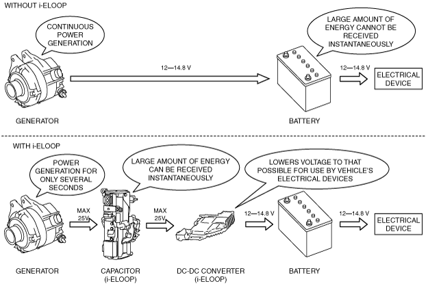
• For improved fuel economy, electrical power is generated using kinetic energy during deceleration and retrieved as electrical energy, which decreases the amount of fuel used for supplying power.
• The Mazda-unique regenerative braking system* stores large quantities of energy instantly during deceleration using a Capacitor (i-ELOOP) which can be tapped quickly for use. Through efficient regenerative braking, storage and use, effective fuel economy improvement during actual driving can be expected.
* :The regenerative braking system is a mechanism for converting kinetic energy during deceleration to electrical energy and storing it for reuse. The electricity stored from the regenerative braking is re-used as power for electrical devices such as the A/C and audio, which decreases the fuel consumption amount required by the engine to supply power.
Structural View
• i-ELOOP consists mainly of the following parts.
|
Capacitor (i-ELOOP)
|
|
|
DC-DC converter (i-ELOOP)
|
|
|
Generator
|
|
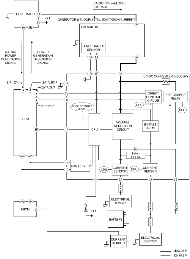
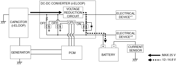
System Wiring Diagram
*1 :Audio amplifer, Bluetooh unit (Vehicle with Bluetooh system), Audio unit, Climate control unit (Vehicle with auto A/C), Parking sensor control module (Vehicle with parking sensor system), Instrument cluster, Rear mount camera, Clock (Vehicle with manual A/C)
*2 :Electrical devices other than electrical device*1
*3 :SKYACTIV-G 2.0, SKYACTIV-G 2.5
*4 :SKYACTIV-D 2.2
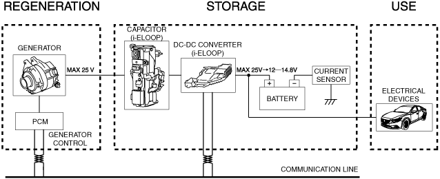
Operation
• The operation aspect of i-ELOOP is as follows.
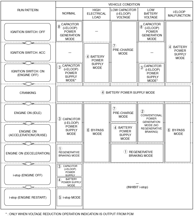
• The i-ELOOP operation mode varies depending on the vehicle driving conditions and the conditions of i-ELOOP-related parts.
|
Condition
|
Operation mode
|
Reference
|
|
Regeneration, storage
|
1.Regenerative braking mode
|
|
|
2. Conventional power generation mode (no regenerative braking)
|
|
|
Use
|
3. Capacitor (i-ELOOP) power supply mode
|
|
|
4. Battery power supply mode
|
|
|
5. i-stop mode
|
|
|
6. By-pass mode
|
|
|
Other mode
|
7. Pre-charge mode
|
|
|
8. Capacitor (i-ELOOP) power generation mode
|
|
1. Regenerative braking mode
-
Purpose
-
• In driving scenarios not using fuel, fuel economy is improved by the generator producing electricity.
-
Operation condition
-
• During fuel-cut by release of accelerator pedal and TCC engagement
-
Operation content
-
• Generator operates at full capacity and stores electricity in the Capacitor (i-ELOOP). The voltage stored in the Capacitor (i-ELOOP) is lowered by the DC-DC converter and electrical power is supplied to the vehicle electrical parts.
*1 :Audio amplifer, Bluetooh unit (Vehicle with Bluetooh system), Audio unit, Climate control unit (Vehicle with auto A/C), Parking sensor control module (Vehicle with parking sensor system), Instrument cluster, Rear mount camera, Clock (Vehicle with manual A/C)
*2 :Electrical devices other than electrical device*1
2. Conventional power generation mode (no regenerative braking)
-
Purpose
-
• During constant/acceleration travel, battery stability is maintained by the power generated by the generator.
-
Operation condition
-
• During engine rotation, battery voltage is certain value or less
-
Operation content
-
• Generator operates and 12 to 25 V of electrical power is stored in the Capacitor (i-ELOOP). The voltage stored in the Capacitor (i-ELOOP) is lowered by the DC-DC converter and electrical power is supplied to the vehicle electrical devices. (Compared to regenerative braking mode, amount of power generated by generator is low.)
*1 :Audio amplifer, Bluetooh unit (Vehicle with Bluetooh system), Audio unit, Climate control unit (Vehicle with auto A/C), Parking sensor control module (Vehicle with parking sensor system), Instrument cluster, Rear mount camera, Clock (Vehicle with manual A/C)
*2 :Electrical devices other than electrical device*1
3. Capacitor (i-ELOOP) power supply mode
-
Purpose
-
• Electrical power is supplied to vehicle electrical devices from the Capacitor (i-ELOOP).
-
Operation condition
-
• Capacitor (i-ELOOP) voltage certain value or more
-
Operation content
-
• The voltage stored in the Capacitor (i-ELOOP) is lowered by the DC-DC converter and electrical power is supplied to vehicle electrical devices.
*1 :Audio amplifer, Bluetooh unit (Vehicle with Bluetooh system), Audio unit, Climate control unit (Vehicle with auto A/C), Parking sensor control module (Vehicle with parking sensor system), Instrument cluster, Rear mount camera, Clock (Vehicle with manual A/C)
*2 :Electrical devices other than electrical device*1
4. Battery power supply mode
-
Purpose
-
• Electrical power is supplied to vehicle electrical devices from the battery.
-
Operation condition
-
• Capacitor (i-ELOOP) voltage certain value or less, or during cranking.
-
Operation content
-
• The same as on contemporary vehicles, electrical power is supplied to vehicle electrical devices from the battery.
*1 :Audio amplifer, Bluetooh unit (Vehicle with Bluetooh system), Audio unit, Climate control unit (Vehicle with auto A/C), Parking sensor control module (Vehicle with parking sensor system), Instrument cluster, Rear mount camera, Clock (Vehicle with manual A/C)
*2 :Electrical devices other than electrical device*1
5. i-stop mode (Engine restart)
-
Purpose
-
• During engine restarting using i-stop, the power supply source is divided between the battery and Capacitor (i-ELOOP) to assure a supply of power to the vehicle’s electrical devices.
-
Operation condition
-
• Engine restarting by i-stop
-
Operation content
-
• The i-stop relay in the DC-DC converter turns off and electrical power from the Capacitor (i-ELOOP) for the battery in which the voltage has decreased by engine cranking is not supplied. As a result, mainly the battery supplies electrical power for the starter, enabling the Capacitor (i-ELOOP) to supply electrical power stable to the vehicle’s electrical devices.
*1 :Audio amplifer, Bluetooh unit (Vehicle with Bluetooh system), Audio unit, Climate control unit (Vehicle with auto A/C), Parking sensor control module (Vehicle with parking sensor system), Instrument cluster, Rear mount camera, Clock (Vehicle with manual A/C)
*2 :Electrical devices other than electrical device*1
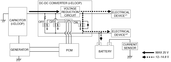
6. By-pass mode
-
Note
-
• During by-pass mode, verification is not possible using the instrument cluster indication.
• If high-capacity audio or additional electrical devices are connected, the by-pass mode may operate frequently due to the increase in the vehicle electrical load.
-
Purpose
-
• If the vehicle electrical load exceeds the output limit of the DC-DC converter, power to the vehicle’s electrical devices cannot be assured, so by operating the by-pass mode, interruption to the operation of the vehicle’s electrical devices is prevented.
-
Operation condition
-
• Vehicle electric load (current consumption) is 50 A or more
• Voltage reduction circuit in DC-DC converter is malfunctioning
• Battery charge condition is less than 65 %
• During DPF regeneration control (SKYACTIV-D 2.2)
-
Operation content
-
• Turns the bypass relay in the DC-DC converter (i-ELOOP) on and the power generated by the generator is also supplied directly to the vehicle’s electrical devices.At this time, the amount of power generated by the generator is suppressed so that power can be supplied directly to the vehicle’s electrical devices.
*1 :Audio amplifer, Bluetooh unit (Vehicle with Bluetooh system), Audio unit, Climate control unit (Vehicle with auto A/C), Parking sensor control module (Vehicle with parking sensor system), Instrument cluster, Rear mount camera, Clock (Vehicle with manual A/C)
*2 :Electrical devices other than electrical device*1
7. Pre-charge mode
-
Note
-
• If the Capacitor (i-ELOOP) continues to self-discharge (vehicle left for long periods with engine not started)/excess back-up current consumption, the pre-charge mode may operate due to the decrease in Capacitor (i-ELOOP) voltage.
-
Purpose
-
• The Capacitor (i-ELOOP) charges for the following two reasons.
-
― If the Capacitor (i-ELOOP) voltage is low, the excitation current to the generator lowers and the generator may not be able to generate power.
― To supply power to the battery from the Capacitor (i-ELOOP), a higher electrical load than the battery is required.
-
Operation condition
-
• If the Capacitor (i-ELOOP) voltage is a certain value or less (stops operation when Capacitor (i-ELOOP) voltage reaches certain value or more.)
-
Operation content
-
• Depending on each type of condition, the method for charging the Capacitor (i-ELOOP) varies.
|
Condition
|
Power supply method
|
Instrument cluster display
|
|
Negative battery cable is connected
|
Power supplied from battery to Capacitor (i-ELOOP)
|
Not applicable
|
|
Ignition switched ON (engine off) while engine is stopped
|
Power supplied from battery to Capacitor (i-ELOOP)
|
Not applicable
|
|
Engine is started
|
Power supplied from generator to Capacitor (i-ELOOP)
|
Applicable
|
-
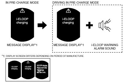
• The PCM sends a message display request signal to the instrument cluster during Capacitor (i-ELOOP) pre-charge when the engine is started.
• If the vehicle is driven while a message is displayed in the LCD, the PCM sends an i-ELOOP warning alarm sound to the instrument cluster.
-
• A message display request signal is sent for a maximum of 3 min and if the message display request condition continues for 3 minutes or more, the PCM sends a master warning light request and message display request to the instrument cluster.
*1 :Audio amplifer, Bluetooh unit (Vehicle with Bluetooh system), Audio unit, Climate control unit (Vehicle with auto A/C), Parking sensor control module (Vehicle with parking sensor system), Instrument cluster, Rear mount camera, Clock (Vehicle with manual A/C)
*2 :Electrical devices other than electrical device*1
8. Capacitor (i-ELOOP) power generation mode
-
Purpose
-
• Surplus power stored in the Capacitor (i-ELOOP) charges the battery.
-
Operation condition
-
• With ignition switched off and bonnet closed, Capacitor (i-ELOOP) voltage is certain voltage or more.
-
Operation content
-
• The voltage stored in the Capacitor (i-ELOOP) is lowered by the DC-DC converter and electrical power is supplied to the battery.
*1 :Audio amplifer, Bluetooh unit (Vehicle with Bluetooh system), Audio unit, Climate control unit (Vehicle with auto A/C), Parking sensor control module (Vehicle with parking sensor system), Instrument cluster, Rear mount camera, Clock (Vehicle with manual A/C)
*2 :Electrical devices other than electrical device*1
• The following are examples of the i-ELOOP operation in each mode.
Instrument cluster display
-
• The PCM sends a regenerative braking condition/regenerative power amount/Capacitor (i-ELOOP) accumulation amount from i-ELOOP to the instrument cluster.
• The instrument cluster displays information related to i-ELOOP in the LCD by the signal received from the PCM.
• The instrument cluster display can be changed using the personalization feature.
|
1
|
Regenerative braking power generation condition gauge
|
Displays the direction in which power is moving from the regenerative braking power generation.
|
|
2
|
Regenerative braking power generation amount gauge
|
Displays the amount of power generated by regenerative braking.
|
|
3
|
Capacitor (i-ELOOP) accumulation amount gauge
|
Displays the amount of electrical power stored in the Capacitor (i-ELOOP).
|
-
Regenerative braking power generation condition gauge
-
• Informs the user of the i-ELOOP operation status.
|
Regenerative braking power generation condition gauge
|
Calculation method
|
|
Screen 1
|
Screen 2
|
|
Not applicable
|
 |
Displays if the i-ELOOP operation stops.
|
 |
 |
Displays when the power used by the vehicle is supplied by the Capacitor (i-ELOOP).
|
 |
 |
Displays when the power generated by regenerative braking is transferred to the Capacitor (i-ELOOP).
|
-
Regenerative braking power generation amount gauge
-
• Displays the amount of electrical power generated by regenerative braking.
|
Regenerative braking power generation amount gauge
|
Calculation method
|
|
Screen 1
|
Screen 2
|
 |
 |
Calculates the amount of electrical power generated by regenerative braking from the power generated by the generator and the Capacitor (i-ELOOP) voltage.
|
-
Capacitor (i-ELOOP) accumulation amount gauge
-
• Displays the amount of electrical power stored in the Capacitor (i-ELOOP).
|
Capacitor (i-ELOOP) accumulation amount gauge
|
Calculation method
|
|
Screen 1
|
Screen 2
|
 |
 |
Calculates the amount of electrical power stored in the Capacitor (i-ELOOP) from the Capacitor (i-ELOOP) voltage and the current sensor in the DC-DC converter.
|
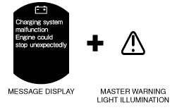
i-ELOOP malfunction indication
-
• If a malfunction occurs in an i-ELOOP-related part, the PCM sends a master warning light illumination request and a message display request in the LCD to the instrument cluster.
PATTERN 1
PATTERN 2