TIMING CHAIN DISASSEMBLY
id011000505500
-
Caution
-
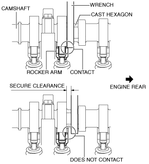
• When rotating the camshaft using a wrench on the cast hexagon, the wrench may contact the rocker arm and damage the rocker arm. To prevent damage to the rocker arm when holding the camshaft on the cast hexagon, use the wrench at engine rear side as shown in the figure to secure a clearance between the cam.
-
Note
-
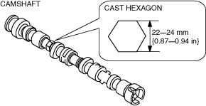
• Width at the cast hexagon of the camshaft is 22—24 mm {0.87—0.94 in}.
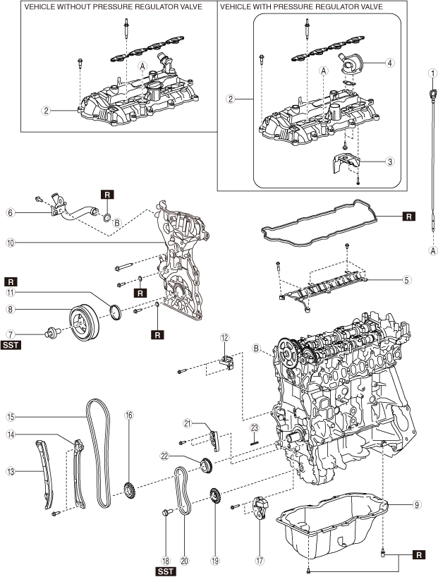
1. Disassemble in the order indicated in the table.
Vehicles with IDEVA (single tensioner type)
|
1
|
Dipstick
|
|
2
|
Cylinder head cover
|
|
3
|
Oil baffle plate
|
|
4
|
Pressure regulator valve
|
|
5
|
Oil shower pipe
|
|
6
|
Water pipe
|
|
7
|
Crankshaft pulley lock bolt
|
|
8
|
Crankshaft pulley
|
|
9
|
Oil pan
|
|
10
|
Engine front cover
|
|
11
|
Front oil seal
|
|
12
|
Timing chain tensioner
|
|
13
|
Timing chain tensioner arm
|
|
14
|
Timing chain guide
|
|
15
|
Timing chain
|
|
16
|
Crankshaft sprocket
|
|
17
|
Oil pump chain tensioner
|
|
18
|
Oil pump driven sprocket installation bolt
|
|
19
|
Oil pump driven sprocket
|
|
20
|
Oil pump chain
|
|
21
|
Oil pump chain guide
|
|
22
|
Oil pump drive sprocket
|
|
23
|
Key
|
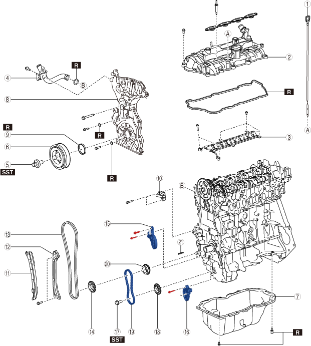
Vehicles with IDEVA (dual tensioner type)
|
1
|
Dipstick
|
|
2
|
Cylinder head cover
|
|
3
|
Oil shower pipe
|
|
4
|
Water pipe
|
|
5
|
Crankshaft pulley lock bolt
|
|
6
|
Crankshaft pulley
|
|
7
|
Oil pan
|
|
8
|
Engine front cover
|
|
9
|
Front oil seal
|
|
10
|
Timing chain tensioner
|
|
11
|
Timing chain tensioner arm
|
|
12
|
Timing chain guide
|
|
13
|
Timing chain
|
|
14
|
Crankshaft sprocket
|
|
15
|
Oil pump chain tensioner No.2
|
|
16
|
Oil pump chain tensioner No.1
|
|
17
|
Oil pump driven sprocket installation bolt
|
|
18
|
Oil pump driven sprocket
|
|
19
|
Oil pump chain
|
|
20
|
Oil pump drive sprocket
|
|
21
|
Key
|
Vehicles without IDEVA
|
1
|
Dipstick
|
|
2
|
Cylinder head cover
|
|
3
|
Oil shower pipe
|
|
4
|
Crankshaft pulley lock bolt
|
|
5
|
Crankshaft pulley
|
|
6
|
Oil pan
|
|
7
|
Engine oil level sensor
|
|
8
|
Engine front cover
|
|
9
|
Front oil seal
|
|
10
|
Timing chain tensioner
|
|
11
|
Timing chain tensioner arm
|
|
12
|
Timing chain guide
|
|
13
|
Timing chain
|
|
14
|
Crankshaft sprocket
|
|
15
|
Oil pump chain tensioner No.2
|
|
16
|
Oil pump chain tensioner No.1
|
|
17
|
Oil pump driven sprocket installation bolt
|
|
18
|
Oil pump driven sprocket
|
|
19
|
Oil pump chain
|
|
20
|
Oil pump drive sprocket
|
|
21
|
Key
|
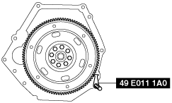
Crankshaft Pulley Lock Bolt Disassembly Note
1. Hold the crankshaft using the SST.
MTX
ATX
2. Remove the crankshaft pulley lock bolt.
Oil Pan Disassembly Note
1. Remove the oil pan using a separator tool.
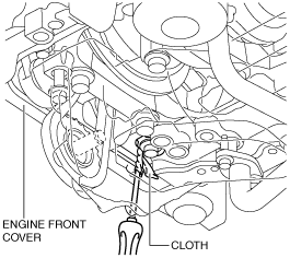
Engine Front Cover Disassembly Note
1. Remove the engine front cover installation bolts.
2. Using a screwdriver wrapped in a cloth, peel the silicone sealant away a little at a time, and remove the engine front cover.
-
Caution
-
• Do not apply excessive force to the screwdriver. Otherwise, the engine front cover could be damaged.
• Be careful not to scratch or damage the seal surface. Otherwise, it could cause oil leakage.
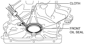
Front Oil Seal Disassembly Note
1. Remove the front oil seal using a flathead screwdriver with the tip protected by a clean cloth.
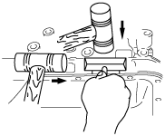
Timing Chain Disassembly Note
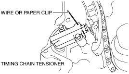
1. Loosen the timing chain tensioner using the following procedure:
- (1) Insert a wire with an approx. diameter of 1.4 mm {0.055 in} or a paper clip into the body hole of the timing chain tensioner.
-
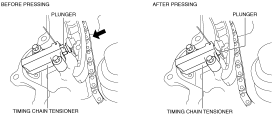
- (2) Press the timing chain in the direction of the arrow and press in the plunger of the timing chain tensioner.
-
- (3) Press the wire or paper clip set in Step 1 further with the plunger pressed.
-
-
Note
-
• The wire or paper clip secures the plunger, and the tension can be released.
2. Remove the timing chain tensioner and timing chain tensioner arm.
3. Remove the timing chain guide.
4. Remove the timing chain and crankshaft sprocket as a single unit.
Oil Pump Chain Disassembly Note
Single tensioner type
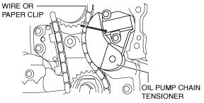
1. Release the tension on oil pump chain using the following procedure.
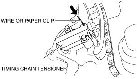
- (1) Press in the plunger of oil pump chain tensioner as shown in the figure using a screwdriver wrapped in a cloth.
-
- (2) Insert a wire with an approx. diameter of 1.4 mm {0.055 in} or a paper clip into the body hole of the oil pump chain tensioner with the plunger pressed.
-
-
Note
-
• The wire or paper clip secures the plunger, and the tension can be released.
2. Remove the oil pump chain tensioner.
3. Remove the oil pump driven sprocket installation bolt using the following procedure.
- (1) Lock the oil pump driven sprocket against rotation using the SST.
-
- (2) Remove the oil pump driven sprocket installation bolt.
-
4. Remove the oil pump chain and oil pump driven sprocket as a single unit.
Dual tensioner type
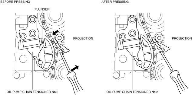
1. Release the tension on oil pump chain using the following procedure.
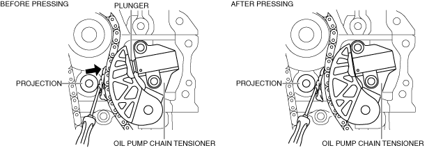
- (1) Press in the plunger of oil pump chain tensioner No.2 as shown in the figure using a screwdriver wrapped in a cloth.
-
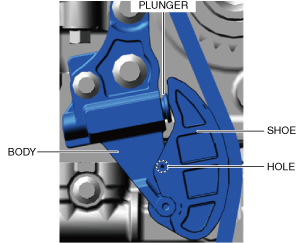
- (2) Insert a wire or paper clip into the shoe hole with the plunger pressed in.
-
-
Note
-
• When inserting a wire or paper clip, the shoe is fixed with the plunger pressed in.
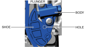
- (3) Press in the plunger of oil pump chain tensioner No.1 as shown in the figure using a screwdriver wrapped in a cloth.
-
- (4) Insert a wire or paper clip into the shoe hole with the plunger pressed in.
-
-
Note
-
• When inserting a wire or paper clip, the shoe is fixed with the plunger pressed in.
2. Remove the oil pump chain tensioner No.1 and No.2.
3. Remove the oil pump driven sprocket installation bolt using the following procedure.
- (1) Lock the oil pump driven sprocket against rotation using the SST.
-
- (2) Remove the oil pump driven sprocket installation bolt.
-
4. Remove the oil pump chain and oil pump driven sprocket as a single unit.