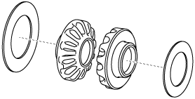
RING GEAR AND DIFFERENTIAL ASSEMBLY [EW6A-EL/EW6AX-EL]


id0517006641l4


Structural View

bfw2za00000201

1
Differential gear case
2
Thrust washer (selection)
3
Side gear
4
Thrust washer
5
Pinion gear
6
Pinion shaft
7
Pin
8
Ring gear
9
12 bolts (M11×1.0 bolt, length to approx. 30 mm {1.2 in})
10
Taper roller bearing
(inner diameter approx. 46 mm {1.8 in})
11
Shim
12
Bearing race*

*  :When replacing the tapered roller bearing on the transaxle side, replace the bearing race with a new one.

Assembly Procedure

1.  Assemble the thrust washers to the side gears.

azzjjw00001535
azzjjw00001536

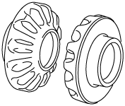
2.  Assemble the side gears which have the thrust washers assembled to them.

bfw2za00000125
bfw2za00000126

3.  Assemble the thrust washers to the pinion gears.

azzjjw00001539
azzjjw00001540

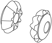
4.  Assemble the pinion gears which have the thrust washers assembled to them using the following procedure:

(1)  Assemble the pinion gears which have the thrust washers assembled to them.
bfw2za00000127
bfw2za00000128
(2)  Rotate the pinion gears so that the pinion shaft holes of the differential gear case and the pinion gears are aligned as shown in the figure.
Note
•  If the pinion shaft holes of the differential gear case and the pinion gears are not aligned, remove the pinion gears, change the side gears combination, and reassemble.
bfw2za00000129

5.  Assemble the pinion shaft.

Caution
•  Assemble the pinion shaft so that the pin holes of the differential gear case and the pinion shaft are aligned.
bfw2za00000130
bfw2za00000131

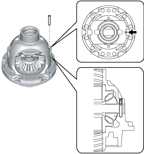
6.  Assemble the pin to the position shown in the figure using a pin punch.

Note
•  Use a pin punch with an end outer diameter of 3.5 mm {0.138 in} or more, and within 5 mm {0.197 in}.
bfw2za00001209

7.  After assembling the pin, crimp the pin hole ends (2 locations) of the differential gear case.

8.  Install the screw used when disassembling to the pin, and verify that the pin cannot be pulled out when pulling the screw.

Note
•  size: M3 x 0.5, length: 10 mm {0.394 in} or more

9.  Assemble the ring gear using the following procedure:

bfw2za00000133

1
Ring gear
2
12 bolts (M11×1.0 bolt, length to approx. 30 mm {1.2 in})

(1)  Assemble the ring gear.
Note
•  Assemble the ring gear so that the differential holes and ring gear holes shown in the figure are aligned.
bfw2za00000134
bfw2za00000135
(2)  Assemble and temporarily tighten the bolts to the positions shown in the figure.
Note
•  Bolt size: M11×1.0 bolt, length to approx. 30 mm {1.2 in}
bfw2za00000136
(3)  Secure the ring gear and differential in a vise.
Caution
•  Insert a protective plate between the vise and the part so as not to damage the part.
bfw2za00000137
A  :Vise
(4)  Tighten the bolts shown in the figure.
Note
•  Change the vise securing position of the ring gear and differential and tighten all of the bolts shown in the figure.
bfw2za00000138
Tightening torque
90.2—98.0 N·m {9.20—9.99 kgf·m, 66.6—72.3 ft·lbf}
(5)  Remove the ring gear and differential from the vise.
bfw2za00000139
A  :Vise

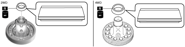
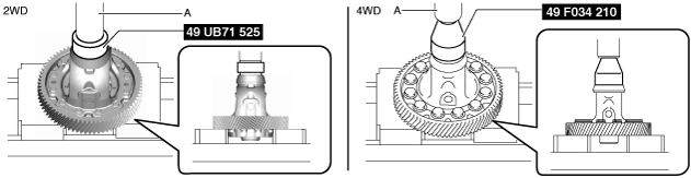
10.  Assemble the taper roller bearing (converter housing side) using the following procedure:

Note
•  Bearing race size: Inner diameter approx. 45 mm {1.8 in} (2WD)
•  Bearing race size: Inner diameter approx. 55 mm {2.2 in} (4WD)
(1)  Apply ATF (ATF FZ) to the engagement area of the taper roller bearing and differential.
(2)  Using the SST and press, assemble the taper roller bearing.
bfw2za00000202
bfw2za00000203
A  :Press

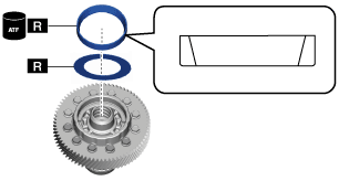
11.  Assemble the shim, bearing race using the following procedure:

Note
•  Bearing race size: outer diameter approx. 90 mm {3.5 in}
(1)  Apply ATF (ATF FZ) to the engagement area of the bearing race and differential.
(2)  Using the SST and press, assemble the bearing race.
bfw2za00000702
bfw2za00000143
A  :Press

12.  Perform the differential backlash measurement/adjustment. (See DIFFERENTIAL BACKLASH MEASUREMENT/ADJUSTMENT [EW6A-EL/EW6AX-EL].)