HIGH CLUTCH CLEARANCE MEASUREMENT/ADJUSTMENT
id051700664600
Preparation Before Servicing
1. Print out the measurement/adjustment value input sheet. (See MEASUREMENT/ADJUSTMENT VALUE INPUT SHEET.)
-
Note
-
• When performing the measurement/adjustment, input the measured and calculated values into the measurement/adjustment value input sheet.
• If the measurement/adjustment value input sheet has already been printed out for the other measurements/adjustments, use the sheet.
High Clutch Clearance Measurement
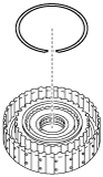
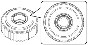
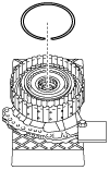
1. Assemble the snap ring.
-
Caution
-
• After assembling the snap ring, verify that the snap ring is securely inserted into the bottom of the snap ring groove.
-
Note
-
• Snap ring size: Outer diameter approx. 144.6 mm {5.693 in}
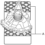
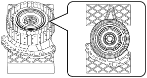
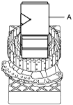
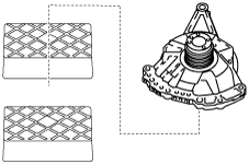
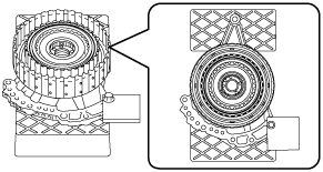
2. Set the oil pump on the workbench as shown in the figure.
-
Caution
-
• To reduce error during the high clutch clearance measurement, use the rubber plates to adjust the alignment surface of the oil pump with the transaxle case so that it is level.
A :Rubber plate
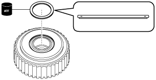
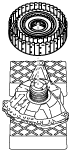
3. Assemble the thrust needle bearing to the clutch component using the following procedure:
-
Note
-
• Thrust needle bearing size: Outer diameter approx. 76.7 mm {3.02 in}
- (1) To prevent the thrust needle bearing from dropping out, apply ATF (ATF FZ) to the thrust needle bearing.
- (2) Assemble the thrust needle bearing.
-
4. Assemble the parts assembled together in Step 3 to the oil pump.
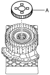
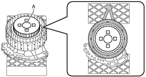
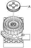
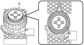
5. Place the reduction internal gear on the retaining plate.
A :Reduction internal gear
A :Reduction internal gear
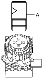
6. Place a 98—196 N {10.0—19.9 kgf, 23.0—44.0 lbf} weight on the reduction internal gear.
-
Caution
-
• To reduce error during the high clutch clearance measurement, place the weight near the center of the reduction internal gear.
-
Note
-
• Use a V-block as a weight.
A :Weight (V-block)
7. Set the measuring instrument to the oil pump using the following procedure:
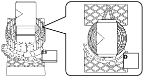
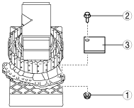
- (1) Install an appropriate steel plate for securing the magnetic stand used in the procedure shown in the figure.
-
-
Caution
-
• If the bolt and nut are tightened with excessive force when installing the steel plate, the alignment surface of the oil pump with the transaxle case could be damaged. Tighten the bolt and nut so that the steel plate does not move during the high clutch clearance measurement.
-
Note
-
• When installing the steel plate to the oil pump, use an M8 bolt and nut.
|
1
|
Steel plate (for securing magnetic stand)
|
|
2
|
Bolt (M8)
|
|
3
|
Nut (M8)
|
-
Steel plate installation bolt tightening torque
-
15 N·m {1.5 kgf·m, 11 ft·lbf} or less (tighten so that steel plate does not move during high clutch clearance measurement)
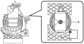
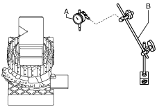
- (2) Set the dial gauge and magnetic stand as shown in the figure.
-
-
Caution
-
• To reduce error during the high clutch clearance measurement, set the dial gauge so that it is perpendicular to the alignment surface of the oil pump with the transaxle case.
A :Dial gauge
B :Magnetic stand
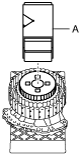
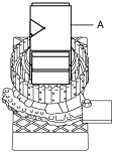
- (3) Set the dial gauge end near the center of the weight.
-
-
Caution
-
• To reduce error during the high clutch clearance measurement, set the dial gauge end within the area shown in the figure.
A :Dial gauge end set area
8. Measure the high clutch clearance using the following procedure:
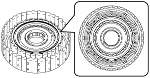
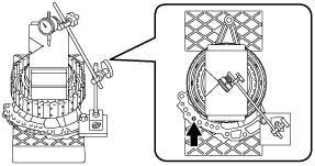
- (1) Blow compressed air into the oil passage shown in the figure to force the high clutch piston to stroke (approx. 3 times).
-
-
Warning
-
• Always wear protective eye wear when using the air compressor. Otherwise, ATF or dirt particles blown off by the air compressor could get into the eyes.
-
Caution
-
• To prevent damage to parts, always use an air compressor which is adjusted to the indicated pressure.
-
Compressed air pressure
-
0.39—0.44 MPa {4.0—4.4 kgf/cm2, 57—63 psi}
- (2) Blow compressed air into the oil passage shown in the figure to operate the high clutch piston, and read the value when the dial gauge is stabilized.
-
-
Warning
-
• Always wear protective eye wear when using the air compressor. Otherwise, ATF or dirt particles blown off by the air compressor could get into the eyes.
-
Caution
-
• To prevent damage to parts, always use an air compressor which is adjusted to the indicated pressure.
-
Compressed air pressure
-
0.39—0.44 MPa {4.0—4.4 kgf/cm2, 57—63 psi}
- (3) Input the dial gauge value, which was read while the high clutch piston was operating, into the measurement/adjustment value input sheet.
- (4) Release the compressed air and read the dial gauge value while the high clutch piston is not operating.
- (5) Input the dial gauge value, which was read while the high clutch piston was not operating, into the measurement/adjustment value input sheet.
- (6) Perform the following calculation to calculate the high clutch clearance.
-
-
High clutch clearance = A - B
-
A: Dial gauge value while high clutch piston is operating
B: Dial gauge value while high clutch piston is not operating
-
Note
-
Example
A: Dial gauge value while high clutch piston is operating is 1.405 mm {0.05532 in}
B: Dial gauge value while high clutch piston is not operating is 0.055 mm {0.00217 in}
High clutch clearance = 1.405 mm {0.05532 in} - 0.055 mm {0.00217 in}= 1.350 mm {0.05315 in}
- (7) Input the calculated high clutch clearance into the measurement/adjustment value input sheet.
- (8) Verify that the high clutch clearance satisfies the specification.
-
-
Specification
-
1.100—1.300 mm {0.04331—0.05118 in}
-
9. Remove the dial gauge and magnetic stand.
A :Dial gauge
B :Magnetic stand
10. Remove the steel plate for securing the magnetic stand using the procedure shown in the figure.
|
1
|
Nut (M8)
|
|
2
|
Bolt (M8)
|
|
3
|
Steel plate (for securing magnetic stand)
|
11. Remove the weight placed on the reduction internal gear.
A :Weight (V-block)
12. Remove the reduction internal gear.
A :Reduction internal gear
13. Remove the clutch component.
14. Remove the thrust needle bearing.
15. Take the oil pump off the rubber plates.
High Clutch Clearance Adjustment
1. Remove the dial gauge and magnetic stand.
A :Dial gauge
B :Magnetic stand
2. Remove the weight placed on the reduction internal gear.
A :Weight (V-block)
3. Remove the reduction internal gear.
A :Reduction internal gear
4. Remove the snap ring.
5. Measure the thickness of the removed snap ring.
-
Note
-
• Recommended measuring instrument: Micrometer
6. Input the measured snap ring thickness into the measurement/adjustment value input sheet.
7. Select the appropriate snap ring from the following table:
|
Range*
|
Selected snap ring thickness
|
|
Exceeds 3.350 mm {0.1319 in}, 3.450 mm {0.1358 in} or less
|
2.2 mm {0.087 in}
|
|
Exceeds 3.250 mm {0.1280 in}, 3.350 mm {0.1319 in} or less
|
2.1 mm {0.083 in}
|
|
Exceeds 3.150 mm {0.1240 in}, 3.250 mm {0.1280 in} or less
|
2.0 mm {0.079 in}
|
|
Exceeds 3.050 mm {0.1201 in}, 3.150 mm {0.1240 in} or less
|
1.9 mm {0.075 in}
|
|
Exceeds 2.950 mm {0.1161 in}, 3.050 mm {0.1201 in} or less
|
1.8 mm {0.071 in}
|
|
Exceeds 2.850 mm {0.1122 in}, 2.950 mm {0.1161 in} or less
|
1.7 mm {0.067 in}
|
|
Exceeds 2.750 mm {0.1083 in}, 2.850 mm {0.1122 in} or less
|
1.6 mm {0.063 in}
|
|
Exceeds 2.650 mm {0.1043 in}, 2.750 mm {0.1083 in} or less
|
1.5 mm {0.059 in}
|
|
Exceeds 2.550 mm {0.1004 in}, 2.650 mm {0.1043 in} or less
|
1.4 mm {0.055 in}
|
|
Exceeds 2.450 mm {0.0965 in}, 2.550 mm {0.1004 in} or less
|
1.3 mm {0.051 in}
|
|
Exceeds 2.350 mm {0.0925 in}, 2.450 mm {0.0965 in} or less
|
1.2 mm {0.047 in}
|
* :The range is the sum of the high clutch clearance and the thickness value of the removed snap ring.
-
Range = C + F
-
C: High clutch clearance
F: Thickness of removed snap ring
-
Note
-
Example
C: High clutch clearance is 1.350 mm {0.05315 in}
F: Thickness of removed snap ring is 1.615 mm {0.06358 in}
Range = 1.350 mm {0.05315 in}+ 1.615 mm {0.06358 in}= 2.965 mm {0.11673 in}, a snap ring of 1.8 mm {0.071 in} thickness should be selected.
8. Assemble the selected snap ring.
-
Caution
-
• After assembling the snap ring, verify that the snap ring is securely inserted into the bottom of the snap ring groove.
-
Note
-
• Snap ring size: Outer diameter approx. 144.6 mm {5.693 in}
9. Place the reduction internal gear on the retaining plate.
A :Reduction internal gear
A :Reduction internal gear
10. Place a 98—196 N {10.0—19.9 kgf, 23.0—44.0 lbf} weight on the reduction internal gear.
-
Caution
-
• To reduce error during the high clutch clearance measurement, place the weight near the center of the reduction internal gear.
-
Note
-
• Use a V-block as a weight.
A :Weight (V-block)
11. Perform the high clutch clearance measurement from Step 7 (2). (See High Clutch Clearance Measurement.)