 |
am6zzn00003222
ON-BOARD DIAGNOSTIC SYSTEM [ELECTRONIC 4WD CONTROL SYSTEM]
id0302a6108100
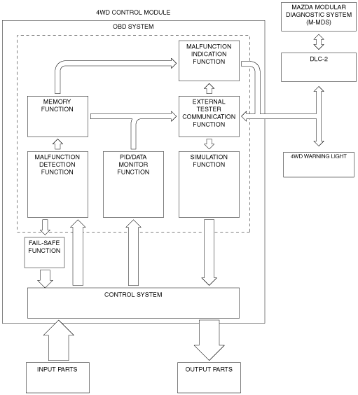
Outline
Block diagram
am6zzn00003222
|
Function
Malfunction detection function
Malfunction indication function
Memory function
DTC table
|
DTC |
4WD warning light |
Description |
Fail-safe |
Drive cycle |
Self test type*1 |
Memory function |
|---|---|---|---|---|---|---|
|
P164D:00
|
Illuminates
|
4WD control module configuration
|
X
|
—
|
C
|
X
|
|
P182F:00
|
flashes
|
4WD control module
|
X
|
—
|
C
|
X
|
|
P187B:00
|
Illuminates
|
4WD control module
|
X
|
—
|
C
|
X
|
|
P1886:00
|
Illuminates
|
4WD control module
|
X
|
—
|
C
|
X
|
|
P1887:11
|
Illuminates
|
System wiring
|
X
|
—
|
C
|
X
|
|
P1887:12
|
Illuminates
|
System wiring
|
X
|
—
|
C
|
X
|
|
P1887:13
|
Illuminates
|
System wiring
|
X
|
—
|
C
|
X
|
|
P1887:14
|
Illuminates
|
System wiring
|
X
|
—
|
C
|
X
|
|
P1888:11
|
Illuminates
|
Differential oil temperature sensor
|
X
|
—
|
C
|
X
|
|
P1888:15
|
Illuminates
|
Differential oil temperature sensor
|
X
|
—
|
C
|
X
|
|
P188A:00
|
flashes
|
4WD control module
|
X
|
—
|
C
|
X
|
|
U0001:88
|
Not illuminate
|
CAN line
|
X
|
—
|
C
|
X
|
|
U0100:00
|
Not illuminate
|
CAN line
|
X
|
—
|
C
|
X
|
|
U0101:00
|
Not illuminate
|
CAN line
|
X
|
—
|
C
|
X
|
|
U0121:00
|
Not illuminate
|
CAN line
|
X
|
—
|
C
|
X
|
|
U0401:68
|
Not illuminate
|
Signal error from PCM
|
X
|
—
|
C
|
X
|
|
U0402:68
|
Not illuminate
|
Signal error from TCM
|
X
|
—
|
C
|
X
|
|
U0415:68
|
Not illuminate
|
Signal error from DSC HU/CM
|
X
|
—
|
C
|
X
|
|
U2100:00
|
Illuminates
|
4WD control module configuration
|
X
|
—
|
C
|
X
|
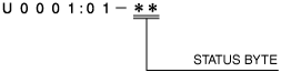
Status byte for DTC
am2zzn00002656
|
Fail-safe function
Fail-safe function table
|
DTC |
4WD control |
|---|---|
|
P164D:00
|
Control maintained by the specified data
|
|
P182F:00
|
Control paused (4WD protection condition)
|
|
P187B:00
|
Control paused (4WD protection condition)
|
|
P1886:00
|
Control disabled
|
|
P1887:11
|
Control disabled
|
|
P1887:12
|
Control disabled
|
|
P1887:13
|
Control disabled
|
|
P1887:14
|
Control disabled
|
|
P1888:11
|
Control disabled
|
|
P1888:15
|
Control disabled
|
|
P188A:00
|
Control paused (4WD protection condition)
|
|
U0001:88
|
Control disabled
|
|
U0100:00
|
Control disabled
|
|
U0101:00
|
Lost gear position signal: Control maintained by the specified data
Except above: Control disabled
|
|
U0121:00
|
Control disabled
|
|
U0401:68
|
Control disabled
|
|
U0402:68
|
Control maintained by the specified data
|
|
U0415:68
|
Control disabled
|
|
U2100:00
|
Control maintained by the specified data
|
Snapshot data
|
Snapshot data item |
Unit |
Definition |
Data read/use method |
Corresponding data monitor items |
|---|---|---|---|---|
|
AAT
|
°C, °F
|
Ambient air temperature
|
—
|
AAT
|
|
IC_VPWR
|
V
|
Instrument cluster power supply
|
• The 4WD control module constantly receives the power supply voltage value of the instrument cluster sent via CAN signal from the instrument cluster.
• If a DTC is detected, the 4WD control module records the power supply voltage of the instrument cluster when the DTC was detected, and it is displayed in the M-MDS.
|
—
|
|
IG-ON_TIMER
|
hh:mm:ss*1
|
Elapsed time since ignition was switched ON
|
• The 4WD control module constantly receives the elapsed time since the ignition was switched ON sent via CAN signal from the instrument cluster.
• If a DTC is detected, the 4WD control module records the elapsed time since the ignition was switched ON when the DTC was detected, and it is displayed in the M-MDS.
|
—
|
|
PWR_MODE_KEY
|
Key Out/Key Recently Out/Key Approved (Position 0)/Post Accessory (Position 0)/Accessory (Position 1)/Post Ignition (Position 1)/Ignition On (Position 2)/Running (Position 2)/Running - Starting In Progress (Position 2)/Crank (Position 3)
|
• Key Out: Ignition switched off
• Key Recently Out (Position 0): Elapsed time within 3 s since ignition was switched off
• Accessory (Position 1): Ignition is switched to ACC
• Post Ignition (Position 2): Elapsed time within 3 s since ignition was switched ON
• Ignition On (Position 2): Ignition switched ON (engine off)
• Running (Position 2): Ignition switched ON (engine on)
• Running - Starting: Cranking condition
|
• The 4WD control module constantly receives the ignition switch status sent via CAN signal from the instrument cluster.
• If a DTC is detected, the 4WD control module records the ignition switch status when the DTC was detected, and it is displayed in the M-MDS.
|
—
|
|
RPM_STATUS
|
Engine Stop/
Under 1500 rpm/
Over 1500 rpm/
FAIL
|
Engine RPM status
|
• The EPS control module constantly receives the ignition switch status sent via CAN signal from the instrument cluster.
• If a DTC is detected, the EPS control module records the ignition switch status when the DTC was detected, and it is displayed in the M-MDS.
|
—
|
|
TOTAL_DIST
|
km, ft, mi
|
Accumulated total traveled distance from completion of vehicle until 4WD control module detects DTC (Odometer value in instrument cluster)
|
The distance traveled when the 4WD control module detected a DTC can be calculated by performing the following procedure.
1. Verify the odometer value in the instrument cluster.
2. Verify the snap shot data item TOTAL_DIST.
3. Subtract 2 from 1.
|
—
|
|
TOTAL_TIME
|
hh:mm:ss*1
|
Accumulated total elapsed time since vehicle completion until 4WD control module detects a DTC
|
The elapsed time when the 4WD control module detected a DTC can be calculated by performing the following procedure.
1. Verify the PID item TOTAL_TIME of the instrument cluster.
2. Verify the snap shot data item TOTAL_TIME.
3. Subtract 2 from 1.
|
—
|
PID/data monitor function
|
Monitor item (Mazda Modular Diagnostic System (M-MDS) display) |
Definition |
Unit/operation |
|---|---|---|
|
AAT
|
Ambient air temperature
|
°C, °F
|
|
APP
|
Accelerator pedal position
|
%
|
|
CAL_TABLE
|
4WD calibration table
|
—
|
|
CUP_SOL
|
4WD solenoid duty cycle
|
%
|
|
GEAR
|
Gear position
|
1st/2nd/3rd/4th/5th/6th/7th/Park/Neutral/Drive/Reverse
|
|
OIL_TEMP
|
Differential oil temperature
|
°C, °F
|
|
RPM
|
Engine speed
|
RPM
|
|
SHIFT
|
Selector lever position
|
P/R/N/D/S/L
|
|
TORQUE
|
Total wheel torque
|
Nm
|
|
VPWR
|
Power supply
|
V
|
|
WARN_LAMP
|
4WD warning light status
|
OFF/ON/Blinking
|
|
WSPD_LF
|
LF ABS wheel-speed sensor
|
KPH, MPH
|
|
WSPD_LR
|
LR ABS wheel-speed sensor
|
|
|
WSPD_RF
|
RF ABS wheel-speed sensor
|
|
|
WSPD_RR
|
RR ABS wheel-speed sensor
|
Simulation function
|
Simulation item |
Output part |
Operation |
Operating condition |
|---|---|---|---|
|
CUP_SOL
|
4WD solenoid
|
OFF/ON
|
Switch the ignition to ON (engine off or on)
|
External tester communication function
|
Diagnostic function name |
Signal received |
Signal sent |
|---|---|---|
|
Malfunction detection function
|
DTC verification signal
|
DTC(s)
|
|
PID/data monitor function
|
Command signal to read selected monitor item
|
Monitored data for requested monitor item
|
|
Simulation function
|
Operation command signal for selected simulation item
|
Output part drive signal
|