 |
ac5uuw00003810
WHEEL HUB COMPONENT REMOVAL/INSTALLATION [4WD]
id0312008004a2
1. Switch the ignition ON (engine off).
2. Release the electric parking brake.
3. Switch the ignition off.
4. When working on the left side of the vehicle, disconnect the auto leveling sensor link. (See AUTO LEVELING SENSOR REMOVAL/INSTALLATION.)
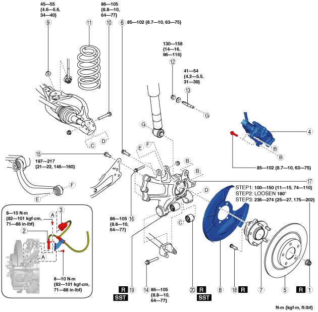
5. Remove in the order indicated in the table.
6. Install in the reverse order of removal.
7. Inspect the rear wheel alignment. (See REAR WHEEL ALIGNMENT.)
ac5uuw00003810
|
|
1
|
Locknut
(See Locknut Removal Note.)
(See Locknut Installation Note.)
|
|
2
|
ABS wheel-speed sensor
|
|
3
|
Electric parking brake motor gear unit connector
|
|
4
|
Brake caliper component
|
|
5
|
Disc plate
|
|
6
|
Bolt (wheel hub)
|
|
7
|
Wheel hub
|
|
8
|
Dust cover
|
|
9
|
Rear stabilizer control link lower side nut
|
|
10
|
Rear lower arm outer bolt
|
|
11
|
Rear coil spring
|
|
12
|
Rear shock absorber lower nut
|
|
13
|
Stud bolt
|
|
14
|
Rear lateral link outer bolt
|
|
15
|
Rear trailing link installation bolt
|
|
16
|
Bolt (rear upper arm outer side)
|
|
17
|
Hub support
|
|
18
|
Wheel hub bolt
|
|
19
|
Hub support bushing (front)
|
|
20
|
Hub support bushing (rear)
|
Locknut Removal Note
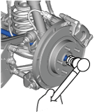
1. Remove the locknut with the brake pedal depressed.
2. Install a spare nut onto the drive shaft.
3. Tap the nut with a copper hammer and separate the drive shaft from the axle.
am6zzw00015569
|
Locknut Installation Note
1. If dust or grease is on the drive shaft thread area, wipe it off with a cloth.
2. Tighten the locknut using the following procedure and with the brake pedal depressed.