am6zzw00009672
|
MASTER CYLINDER REMOVAL/INSTALLATION [R.H.D.]
id041100801352
1. For SKYACTIV-G 2.0 or SKYACTIV-G 2.5, perform the following procedure:
am6zzw00009672
|
2. For SKYACTIV-D 2.2, perform the following procedure:
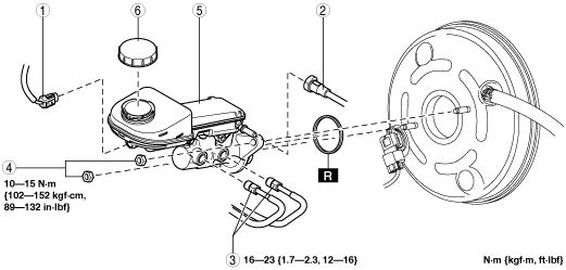
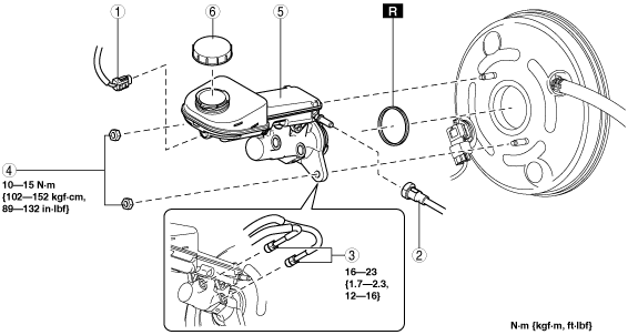
3. Remove in the order indicated in the table.
4. If the master cylinder component is replaced as a single unit, adjust the power brake unit rod. (See Rod Adjustment Note.)
5. Install in the reverse order of removal.
6. After installation, add brake fluid, bleed the air, and inspect for fluid leakage. (See BRAKE FLUID AIR BLEEDING.)
SKYACTIV-G 2.0, SKYACTIV-G 2.5
am6zzw00012689
|
|
1
|
Brake fluid level sensor connector
|
|
2
|
Clutch reserve hose (MTX)
|
|
3
|
Brake pipe
|
|
4
|
Nut
|
|
5
|
Master cylinder component
|
|
6
|
Cap
|
SKYACTIV-D 2.2
am6zzw00012690
|
|
1
|
Brake fluid level sensor connector
|
|
2
|
Clutch reserve hose (MTX)
|
|
3
|
Brake pipe
|
|
4
|
Nut
|
|
5
|
Master cylinder component
|
|
6
|
Cap
|
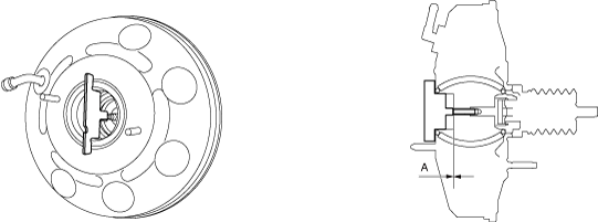
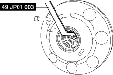
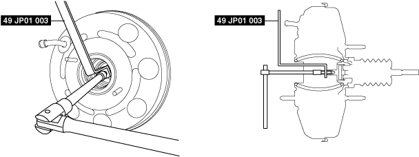
Rod Adjustment Note
1. Install the plate as shown in the figure and verify that the clearance between the rod end and the plate is within the standard.
am6zzw00015400
|
am6zzw00015401
|
am6zzw00015402
|
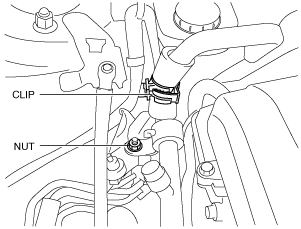
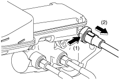
Clutch Reserve Hose Removal Note (MTX)
1. Disconnect the clutch reserve hose in the order shown in the figure.
am6zzw00008901
|
Clutch Reserve Hose Installation Note (MTX)
1. Insert the clutch reserve hose to the master cylinder.
2. Pull the clutch reserve hose to verify that it does not come off, and reinsert it completely.