|
ac5wzn00000240
DYNAMIC STABILITY CONTROL (DSC)
id041500104600
Outline
DSC operation outline
Results of DSC operation
ac5wzn00000240
|
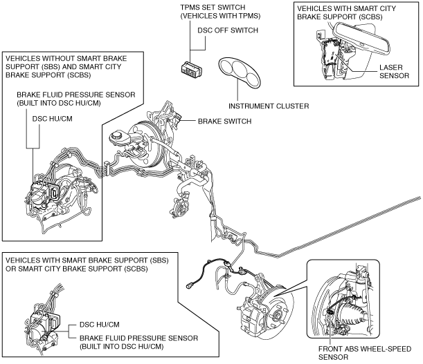
Structural View
Vehicle front side (L.H.D.)
am6zzn00003208
|
Vehicle front side (R.H.D.)
am6zzn00003209
|
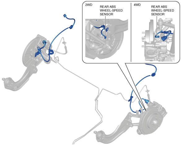
Vehicle rear side
am6zzn00003210
|
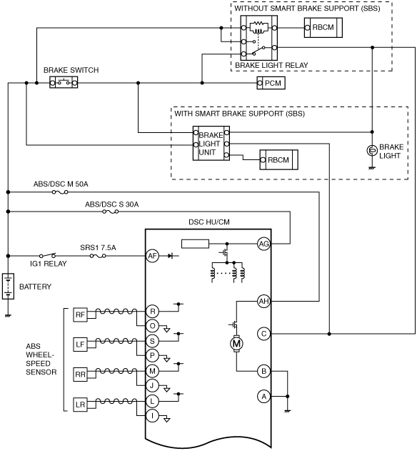
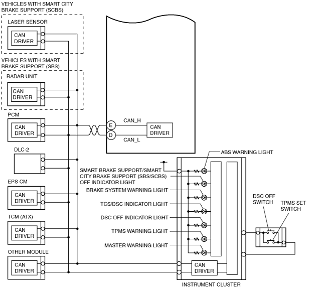
System Wiring Diagram
am6zzn00003994
|
am6zzn00003995
|
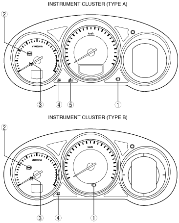
Warning light and indicator light
am6zzn00003503
|
|
No. |
Warning/Indicator lights |
Name |
Function |
|---|---|---|---|
|
1
|
 |
Brake system warning light
|
• When the parking brake has been applied, the warning light illuminates to notify the driver.
• When the ABS control and EBD control are disabled with the parking brake released, the warning light illuminates to notify the driver.
|
|
2
|
 |
ABS warning light
|
• When the ABS control is disabled, the warning light illuminates to notify the driver.
|
|
3
|
 |
TCS/DSC indicator light
|
• When the TCS is operated (drive wheel is slipping), the indicator light flashes to notify the driver.
• When the DSC is operated (vehicle side-slip condition), the indicator light flashes to notify the driver.
• When the DSC systemis malfunctioned, the warning light illuminates to notify the driver.
|
|
4
|
 |
DSC OFF indicator light
|
• When the TCS/DSC control is disabled by operation of the DSC OFF switch, the indicator light illuminates to notify the driver.
|
|
5
|
 |
Smart brake support/smart city brake support (SBS/SCBS) OFF indicator light
|
• When the Smart city brake support (SCBS) system is disabled at driver descretion or system malfunction, the indicator illuminates to notify the driver.
• When the Smart brake support (SBS) system is disabled at driver descretion or system malfunction, the indicator illuminates to notify the driver.
|
Construction
|
Part name |
Function |
|---|---|
|
DSC HU/CM
|
• Makes calculations using input signals from each sensor, controls brake fluid pressure to each wheel, and actuates function (ABS, EBD, TCS, DSC, brake assist control, vehicle roll prevention function, hill launch assist (HLA), TPMS*1, secondary collision reduction (SCR)*2, smart brake support (SBS)*3, and smart city brake support (SCBS)*4) of the DSC system.
• Outputs the torque reduction request signal, wheel speed signal, and DSC system warning control data via CAN lines.
• Controls the on-board diagnostic system and fail-safe function when there is a malfunction in the DSC system.
|
|
PCM
|
• Controls engine output based on signals from the DSC HU/CM.
• Transmits engine speed, engine torque, brake switch status, and accelerator pedal position data via CAN communication to the DSC HU/CM.
• Transmits gear/shift lever position data via CAN communication to the DSC HU/CM. (MTX)
|
|
TCM (ATX)
|
• Transmits gear/selector lever position data via CAN communication to the DSC HU/CM.
|
|
EPS CM
|
• Transmits steering angle data via CAN communication to the DSC HU/CM.
|
|
SAS control module
|
• Detects the lateral-G (vehicle lateral acceleration speed), the yaw rate (vehicle turning angle speed), and the longitudinal-G (vehicle longitudinal acceleration speed) via CAN communication to the DSC HU/CM.
|
|
Brake system warning light
|
• Notifies the driver that the parking brake is applied.
• Notifies the driver of an ABS or EBD malfunction.
|
|
ABS warning light
|
• Notifies the driver of an ABS malfunction.
|
|
TCS/DSC indicator light
|
• Informs the driver that the TCS is operating (drive wheel is spinning).
• Informs the driver that the DSC is operating (vehicle sideslip occurring).
• Informs the driver of DSC system malfunction.
|
|
DSC OFF switch
|
• Transmits driver intention to release TCS/DSC control to the DSC HU/CM.
|
|
DSC OFF indicator light
|
• Informs driver that TCS/DSC control has been released due to DSC OFF switch operation.
|
|
Smart brake support/Smart city brake support (SBS/SCBS) OFF indicator light
|
• Informs driver that smart brake support/smart city brake support (SBS/SCBS) has been deactivated due to smart brake support/smart city brake support (SBS/SCBS) OFF switch operation or i-ACTIVSENSE personalization.
|
|
TPMS set switch*1
|
• Data initialization after adjusting the tire pressures can be done.
|
|
TPMS warning light*1
|
• Notifies the driver that the tire pressure is not normal.
• Notifies the driver of an TPMS malfunction.
|
|
Master warning light
|
• Informs the driver of DSC system malfunction.
|
|
ABS wheel-speed sensor
|
• Detects the rotation condition of each wheel and transmits it to the DSC HU/CM.
|
|
Brake fluid pressure sensor (Built into DSC HU/CM)
|
• Detects the fluid pressure from the master cylinder.
|
|
Laser sensor*4
|
• Emits near-infrared laser and detects the distance between the vehicle and a vehicle or an obstruction ahead based on the reflection.
|